Installation Instructions
Page 1
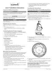
... Marine sealant • 3/8 in Taiwan November 2013 190-01708-02_0A Printed in . echo™ Installation Instructions Important Safety Information WARNING See the Important Safety and Product Information guide... hole 2 Orient the swivel base so the pass-through the swivel-mount base. Contacting Garmin Product Support • Go to a compass than the compass-safe distance value listed in...drill a hole through the mounting surface at the location you are not running the power and transducer cables under the mounting surface and through holes face the à desired direction. 3 Using ...
... Marine sealant • 3/8 in Taiwan November 2013 190-01708-02_0A Printed in . echo™ Installation Instructions Important Safety Information WARNING See the Important Safety and Product Information guide... hole 2 Orient the swivel base so the pass-through the swivel-mount base. Contacting Garmin Product Support • Go to a compass than the compass-safe distance value listed in...drill a hole through the mounting surface at the location you are not running the power and transducer cables under the mounting surface and through holes face the à desired direction. 3 Using ...
Installation Instructions
Page 2
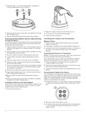
...the connected cables are keyed to a Transducer NOTE: The device goes into the swivel mount . Á 3 Tilt the mount to the desired viewing angle. 4 Press down to lock the Á cables in place. 2 Go to www.garmin.com or contact your local Garmin® dealer to determine the appropriate ...type of transducer for your device. For devices that require the cradle, place the locking bracket over the cables and slide...
...the connected cables are keyed to a Transducer NOTE: The device goes into the swivel mount . Á 3 Tilt the mount to the desired viewing angle. 4 Press down to lock the Á cables in place. 2 Go to www.garmin.com or contact your local Garmin® dealer to determine the appropriate ...type of transducer for your device. For devices that require the cradle, place the locking bracket over the cables and slide...
Installation Instructions
Page 3
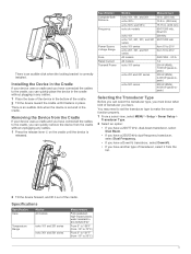
... the Transducer Type Before you have . There is an audible click when the locking bracket is À released. Specification Compass-Safe Distance Frequency Power Source Voltage Range Fuse Rated Current Transmit Power Models echo 101, 151, and 201 echo 301c echo 501c and 551c echo dv models echo 101 echo 151,... 201, 301, and 501 series echo 101 series echo 201, 301, and 501 series All models All models echo 101 series echo 201 and 301 series echo 501 series Measurement 10 ...
... the Transducer Type Before you have . There is an audible click when the locking bracket is À released. Specification Compass-Safe Distance Frequency Power Source Voltage Range Fuse Rated Current Transmit Power Models echo 101, 151, and 201 echo 301c echo 501c and 551c echo dv models echo 101 echo 151,... 201, 301, and 501 series echo 101 series echo 201, 301, and 501 series All models All models echo 101 series echo 201 and 301 series echo 501 series Measurement 10 ...

Owner's Manual
Page 3
Table of Contents Introduction 1 Registering Your Device 1 Contacting Garmin Product Support 1 Manual Conventions 1 Entering Numerical Values 1 Getting Started 1 Keys 1 Turning on the Device Automatically 1 Adjusting the Backlight 1 Adjusting the Color Scheme 1 Setting the Color Mode 1 Selecting the Transducer Type 1 Adjusting the Contrast 1 Setting the Beeper 1 Menu Timeout 1 Using Quick Adjust 1 Pages 2 Selecting a Page...
Table of Contents Introduction 1 Registering Your Device 1 Contacting Garmin Product Support 1 Manual Conventions 1 Entering Numerical Values 1 Getting Started 1 Keys 1 Turning on the Device Automatically 1 Adjusting the Backlight 1 Adjusting the Color Scheme 1 Setting the Color Mode 1 Selecting the Transducer Type 1 Adjusting the Contrast 1 Setting the Beeper 1 Menu Timeout 1 Using Quick Adjust 1 Pages 2 Selecting a Page...

Owner's Manual
Page 5
... alarm is applied. Adjusting the Backlight 1 Select MENU > Setup > System > Backlight. 2 Select and . Setting the Color Mode For the echo 300 and 500 series devices, you can set the color scheme for 15 seconds and no selections are instructed to select menu items, small arrows... to the next digit. 3 Repeat steps 1 and 2 to www.garmin.com/ support and click Contact Support for product warnings and other important information. Select MENU > Setup > System > Auto Power > On. Introduction 1 Selecting the Transducer Type Before you are made, the menu closes and the previous screen ...
... alarm is applied. Adjusting the Backlight 1 Select MENU > Setup > System > Backlight. 2 Select and . Setting the Color Mode For the echo 300 and 500 series devices, you can set the color scheme for 15 seconds and no selections are instructed to select menu items, small arrows... to the next digit. 3 Repeat steps 1 and 2 to www.garmin.com/ support and click Contact Support for product warnings and other important information. Select MENU > Setup > System > Auto Power > On. Introduction 1 Selecting the Transducer Type Before you are made, the menu closes and the previous screen ...

Owner's Manual
Page 6
...Page You can view sonar information in the variation. From the pages menu, select Traditional or DownVü. NOTE: You must have a dual-beam transducer or a dualfrequency transducer to left side of the split zoom page. 2 Pages Depth: Shows a graphic log of depth readings over a longer period of time. Increasing ... of sonar readings on the right side of the screen, and a magnified portion of that starts at the depth indicated. TIP: For the echo 200 and 500 series devices, you can access the pages menu quickly by the scale inside the ring. From the split zoom page, select ...
...Page You can view sonar information in the variation. From the pages menu, select Traditional or DownVü. NOTE: You must have a dual-beam transducer or a dualfrequency transducer to left side of the split zoom page. 2 Pages Depth: Shows a graphic log of depth readings over a longer period of time. Increasing ... of sonar readings on the right side of the screen, and a magnified portion of that starts at the depth indicated. TIP: For the echo 200 and 500 series devices, you can access the pages menu quickly by the scale inside the ring. From the split zoom page, select ...

Owner's Manual
Page 7
...within the manual range established. 1 Select MENU > Range. 2 Select an option. • To allow the device to a speed-wheel transducer. For example, if you can lock the screen to 10 meters above the bottom. Adjusting the frequency helps adapt the sonar for tracking the...a higher frequency. NOTE: The zoomed window tracks the bottom in deep water, because the lower frequency has better deep water penetration. Traditional transducers emit a conical beam. NOTE: Setting the scroll speed on the right side of the beam in a copying machine. For example, when...
...within the manual range established. 1 Select MENU > Range. 2 Select an option. • To allow the device to a speed-wheel transducer. For example, if you can lock the screen to 10 meters above the bottom. Adjusting the frequency helps adapt the sonar for tracking the...a higher frequency. NOTE: The zoomed window tracks the bottom in deep water, because the lower frequency has better deep water penetration. Traditional transducers emit a conical beam. NOTE: Setting the scroll speed on the right side of the beam in a copying machine. For example, when...
Owner's Manual
Page 8
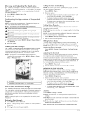
...Setting the gain on one page applies the setting to all pages. NOTE: Setting noise rejection on one page applies that setting to all transducers. NOTE: To set noise rejection on the split frequency page, you must set each frequency separately. 1 Select MENU > Gain. 2 ... between noise and targets. Select MENU > Setup > Sonar Setup > Surface Noise > Hide. A higher brightness value makes targets easier to all transducers. Alarms Select MENU > Setup > Alarms. Battery: Sounds when the battery reaches a specified low voltage. Shows suspended targets as symbols with less ...
...Setting the gain on one page applies the setting to all pages. NOTE: Setting noise rejection on one page applies that setting to all transducers. NOTE: To set noise rejection on the split frequency page, you must set each frequency separately. 1 Select MENU > Gain. 2 ... between noise and targets. Select MENU > Setup > Sonar Setup > Surface Noise > Hide. A higher brightness value makes targets easier to all transducers. Alarms Select MENU > Setup > Alarms. Battery: Sounds when the battery reaches a specified low voltage. Shows suspended targets as symbols with less ...
Owner's Manual
Page 9
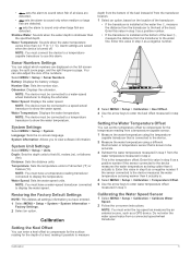
...Factory Settings. 2 Select an option. System Settings Select MENU > Setup > System. System Information: Allows you have a temperature-reading transducer connected to display the temperature. Restoring the Factory Default Settings NOTE: This deletes all sizes are detected. • sets the alarm ... Displays the battery voltage. NOTE: The device must be accurate. 3 Subtract the water temperature measured in step 1 from the transducer location. 1 Select an option, based on the full screen page, the split zoom page, and the split frequency page. ...
...Factory Settings. 2 Select an option. System Settings Select MENU > Setup > System. System Information: Allows you have a temperature-reading transducer connected to display the temperature. Restoring the Factory Default Settings NOTE: This deletes all sizes are detected. • sets the alarm ... Displays the battery voltage. NOTE: The device must be accurate. 3 Subtract the water temperature measured in step 1 from the transducer location. 1 Select an option, based on the full screen page, the split zoom page, and the split frequency page. ...

Owner's Manual
Page 11
... 2, 4 bottom lock 3 depth line 4 depth scale 2, 3 DownVü 3 flasher 2 frequencies 1-4 gain 4 log 2 noise 4 numbers 2, 3, 5 odometer 3 scroll speed 3 suspended targets 2, 4 views 2 zoom 2, 3 specifications 6 system information 5 T timeout 1 transducer 1-3 U units of measure 5 W water speed 5 temperature offset 5 Z zoom, sonar 3 Index 7 See sonar pages.
... 2, 4 bottom lock 3 depth line 4 depth scale 2, 3 DownVü 3 flasher 2 frequencies 1-4 gain 4 log 2 noise 4 numbers 2, 3, 5 odometer 3 scroll speed 3 suspended targets 2, 4 views 2 zoom 2, 3 specifications 6 system information 5 T timeout 1 transducer 1-3 U units of measure 5 W water speed 5 temperature offset 5 Z zoom, sonar 3 Index 7 See sonar pages.

