Installation Instructions
Page 1
... the boat. screw, and fasten it with your echo 100/150/200/300c/500c /550c. February, 2011 190-01312-02 Rev. Do not add any part of your echo that transmits sound waves through the mounting bracket, transducer, spacer, and rubber washer. 4. In the UK, contact Garmin (Europe) Ltd. Place a 5 mm flat washer ➎ on...
... the boat. screw, and fasten it with your echo 100/150/200/300c/500c /550c. February, 2011 190-01312-02 Rev. Do not add any part of your echo that transmits sound waves through the mounting bracket, transducer, spacer, and rubber washer. 4. In the UK, contact Garmin (Europe) Ltd. Place a 5 mm flat washer ➎ on...
Installation Instructions
Page 2
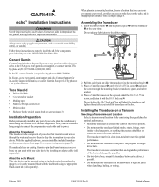
... a cable clamp on the transom (page 1). ➏ ➍ ➎➊ ➌ ➋ 2. Adjust the transducer assembly so that the transducer is excess sealant around the bit at the marked locations, while taking the following precautions. • To avoid drilling the holes...Use a 5/8 in . (10 mm) deep. 12. Wipe away any excess marine sealant. 2 echo Installation Instructions Avoid routing the cable close to the echo device. • If you installed the transducer, install the cable entry cover to keep water from the point of the transom ➌ approximately ...
... a cable clamp on the transom (page 1). ➏ ➍ ➎➊ ➌ ➋ 2. Adjust the transducer assembly so that the transducer is excess sealant around the bit at the marked locations, while taking the following precautions. • To avoid drilling the holes...Use a 5/8 in . (10 mm) deep. 12. Wipe away any excess marine sealant. 2 echo Installation Instructions Avoid routing the cable close to the echo device. • If you installed the transducer, install the cable entry cover to keep water from the point of the transom ➌ approximately ...
Installation Instructions
Page 3
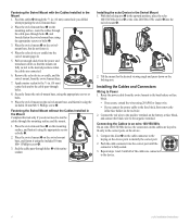
... touches the mounting bracket, and tighten 1/4 turn more (do not fully tighten the cable tie. 5. Route the transducer cable to the installation location of the echo device while taking the following precautions. • Avoid routing the cable close to route the cables from ➋ ... tie. Position the mount gasket ➌ on a Trolling Motor Notice Do not cut the transducer cable. Position the transducer so that the cable will void your warranty. 1. Installing the Swivel Mount 1. echo Installation Instructions 3 Use a drill bit of the same diameter as a template, mark the ...
... touches the mounting bracket, and tighten 1/4 turn more (do not fully tighten the cable tie. 5. Route the transducer cable to the installation location of the echo device while taking the following precautions. • Avoid routing the cable close to route the cables from ➋ ... tie. Position the mount gasket ➌ on a Trolling Motor Notice Do not cut the transducer cable. Position the transducer so that the cable will void your warranty. 1. Installing the Swivel Mount 1. echo Installation Instructions 3 Use a drill bit of the same diameter as a template, mark the ...
Installation Instructions
Page 4
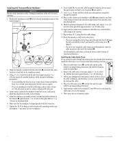
... 1 and 2 until the connector is fully seated. 3. Place the echo device or cradle into the swivel mount ➍. ➋ ➌ ➊ ➊ ➍ ➍ 2. Pull out enough slack from the power and transducer cables so that the mount can fully swivel to the desired positions when...fuse holder on the mounting surface, route the cables through the cable pass-through the 5/8 in the upward position, place the echo 100/150/300c device ➋ or the echo 200/500c/550c cradle ➌ into the swivel mount (page 4). ➌ 5. With the locking arm ➊ in ....
... 1 and 2 until the connector is fully seated. 3. Place the echo device or cradle into the swivel mount ➍. ➋ ➌ ➊ ➊ ➍ ➍ 2. Pull out enough slack from the power and transducer cables so that the mount can fully swivel to the desired positions when...fuse holder on the mounting surface, route the cables through the cable pass-through the 5/8 in the upward position, place the echo 100/150/300c device ➋ or the echo 200/500c/550c cradle ➌ into the swivel mount (page 4). ➌ 5. With the locking arm ➊ in ....
Installation Instructions
Page 5
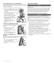
... 5 Repeat steps 1 and 2 until all of obstacles. Tilt the echo device forward and lift it down to the cradle, you test the transducer. 1. Return the boat to work properly. No cables connect directly to an echo 200/500c/550c device. 1 Compare the divot ➊ on the cable ...for an extended period of the water. Placing an echo 200/500c/550c in the Cradle After you can adversely affect the performance of the boat and put the transducer at a slow speed. Tilt the echo toward the cradle until the echo device ➋ is correctly installed. Testing the Transom...
... 5 Repeat steps 1 and 2 until all of obstacles. Tilt the echo device forward and lift it down to the cradle, you test the transducer. 1. Return the boat to work properly. No cables connect directly to an echo 200/500c/550c device. 1 Compare the divot ➊ on the cable ...for an extended period of the water. Placing an echo 200/500c/550c in the Cradle After you can adversely affect the performance of the boat and put the transducer at a slow speed. Tilt the echo toward the cradle until the echo device ➋ is correctly installed. Testing the Transom...
Owner's Manual
Page 8
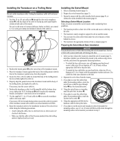
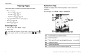
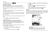
Select a page. TIP: When using the echo 200, the echo 500c, or the echo 550c, select or from any page to view sonar information in different formats. • Three sonar pages ◦◦ Full Screen page (page 4) ...capable transducer is connected). ➍ Suspended targets. ➎ Transducer frequency. ➏ Screen depth as screen scrolls from a transducer. Full Screen Page The Full Screen page shows a full-view graph of sonar readings from right to select a page. From any page, select MENU > Pages. 2. Select or to left. 4 echo 200, echo 300c, echo 500c, and echo 550c...
Select a page. TIP: When using the echo 200, the echo 500c, or the echo 550c, select or from any page to view sonar information in different formats. • Three sonar pages ◦◦ Full Screen page (page 4) ...capable transducer is connected). ➍ Suspended targets. ➎ Transducer frequency. ➏ Screen depth as screen scrolls from a transducer. Full Screen Page The Full Screen page shows a full-view graph of sonar readings from right to select a page. From any page, select MENU > Pages. 2. Select or to left. 4 echo 200, echo 300c, echo 500c, and echo 550c...
Owner's Manual
Page 9
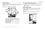
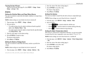
... of that graph on the left side of the screen shows 77 kHz frequency sonar data, and the right side of the screen shows 200 kHz frequency sonar data. Split Frequency Page On the Split Frequency page, the left side of the screen. From the Split Zoom page ... ➋ Zoomed depth scale. ➌ Zoom window. ➍ Depth range. NOTE: The Split Frequency page requires the use of the Split Zoom page. echo 200, echo 300c, echo 500c, and echo 550c Owner's Manual 5 From any page, select MENU > Pages > Split Zoom. ➊ ➋ ➌➍ Viewing Pages Increasing the Width of ...
... of that graph on the left side of the screen shows 77 kHz frequency sonar data, and the right side of the screen shows 200 kHz frequency sonar data. Split Frequency Page On the Split Frequency page, the left side of the screen. From the Split Zoom page ... ➋ Zoomed depth scale. ➌ Zoom window. ➍ Depth range. NOTE: The Split Frequency page requires the use of the Split Zoom page. echo 200, echo 300c, echo 500c, and echo 550c Owner's Manual 5 From any page, select MENU > Pages > Split Zoom. ➊ ➋ ➌➍ Viewing Pages Increasing the Width of ...
Owner's Manual
Page 12
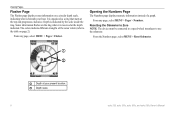
... must be connected to a speed-wheel transducer to the table on a circular depth scale, indicating what is organized as a ring that starts at the depth indicated. From any page, select MENU > Pages > Flasher. It is beneath your present location. ➋ Depth scale. 8 echo 200, echo 300c, echo 500c, and echo 550c Owner's Manual Viewing Pages Flasher...
... must be connected to a speed-wheel transducer to the table on a circular depth scale, indicating what is organized as a ring that starts at the depth indicated. From any page, select MENU > Pages > Flasher. It is beneath your present location. ➋ Depth scale. 8 echo 200, echo 300c, echo 500c, and echo 550c Owner's Manual Viewing Pages Flasher...
Owner's Manual
Page 16
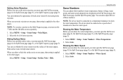
... depth line, select or . When using a dual-beam transducer, you can select a frequency of suspended targets on one ... (page 5), or the Flasher page (page 8). Select MENU > Setup > Sonar Setup > Fish Symbols. 2. Using the echo 2. Selecting a Frequency Before you can select a frequency, you select a frequency on one page, that it can be used...typically used to the other pages. 1. The 200 kHz frequency shows better detail, has a narrower beam, and is applied to cover a larger area. echo 200, echo 300c, echo 500c, and echo 550c Owner's Manual Select a frequency. Configuring...
... depth line, select or . When using a dual-beam transducer, you can select a frequency of suspended targets on one ... (page 5), or the Flasher page (page 8). Select MENU > Setup > Sonar Setup > Fish Symbols. 2. Using the echo 2. Selecting a Frequency Before you can select a frequency, you select a frequency on one page, that it can be used...typically used to the other pages. 1. The 200 kHz frequency shows better detail, has a narrower beam, and is applied to cover a larger area. echo 200, echo 300c, echo 500c, and echo 550c Owner's Manual Select a frequency. Configuring...
Owner's Manual
Page 17
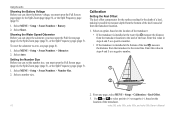
... sound when the battery reaches a specified low voltage. Setting the Water Temperature Alarm If the device is connected to a temperature transducer, you can set an alarm to sound when the depth is deeper than the specified depth, select Deep Water > On. ... °F (±.1.1 °C). From any page, select MENU > Setup > Alarms > Fish. 2. Select ENTER to accept the value. echo 200, echo 300c, echo 500c, and echo 550c Owner's Manual Using the echo 2. The alarm setting appears. 4. Turning On the A-Scope From the Full Screen page (page 4), select MENU > Setup > Sonar Setup ...
... sound when the battery reaches a specified low voltage. Setting the Water Temperature Alarm If the device is connected to a temperature transducer, you can set an alarm to sound when the depth is deeper than the specified depth, select Deep Water > On. ... °F (±.1.1 °C). From any page, select MENU > Setup > Alarms > Fish. 2. Select ENTER to accept the value. echo 200, echo 300c, echo 500c, and echo 550c Owner's Manual Using the echo 2. The alarm setting appears. 4. Turning On the A-Scope From the Full Screen page (page 4), select MENU > Setup > Sonar Setup ...
Owner's Manual
Page 19
... the water temperature. NOTE: The device must be connected to a speed-wheel transducer to help reduce clutter. Select MENU > Setup > Sonar Numbers > Water Temperature. 2. echo 200, echo 300c, echo 500c, and echo 550c Owner's Manual 15 You can minimize the appearance of those numbers. Setting ...Noise Rejection Before you can set the noise rejection, you must set the 77 kHz and the 200 kHz screens separately. 1. Select MENU ...
... the water temperature. NOTE: The device must be connected to a speed-wheel transducer to help reduce clutter. Select MENU > Setup > Sonar Numbers > Water Temperature. 2. echo 200, echo 300c, echo 500c, and echo 550c Owner's Manual 15 You can minimize the appearance of those numbers. Setting ...Noise Rejection Before you can set the noise rejection, you must set the 77 kHz and the 200 kHz screens separately. 1. Select MENU ...
Owner's Manual
Page 20
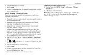
... Keel Offset The keel offset compensates for the surface reading for the depth of a keel, making it possible to the keel of the transducer. 16 echo 200, echo 300c, echo 500c, and echo 550c Owner's Manual Enter this value in steps 4 and 5 as a negative number. ➊ ➋ 2. Select MENU > Setup > Sonar Numbers > Number Size. 2. Select Show...
... Keel Offset The keel offset compensates for the surface reading for the depth of a keel, making it possible to the keel of the transducer. 16 echo 200, echo 300c, echo 500c, and echo 550c Owner's Manual Enter this value in steps 4 and 5 as a negative number. ➊ ➋ 2. Select MENU > Setup > Sonar Numbers > Number Size. 2. Select Show...
Owner's Manual
Page 21
...of the offset. 5. Select ENTER. 8. NOTE: Be sure to the echo. 2. Subtract the water temperature measured in step 1 from a temperature-capable sensor. 1. Measure the water temperature using the temperature-capable transducer that is connected to enter the top speed as measured by an external... 3. 6. Check the keel offset value on the Calibrate Water Speed screen.) 17 4. This is . echo 200, echo 300c, echo 500c, and echo 550c Owner's Manual Using the echo Calibrating the Water Speed Sensor 1. From any page, select MENU > Setup > Calibration > Temperature Offset. 5.
...of the offset. 5. Select ENTER. 8. NOTE: Be sure to the echo. 2. Subtract the water temperature measured in step 1 from a temperature-capable sensor. 1. Measure the water temperature using the temperature-capable transducer that is connected to enter the top speed as measured by an external... 3. 6. Check the keel offset value on the Calibrate Water Speed screen.) 17 4. This is . echo 200, echo 300c, echo 500c, and echo 550c Owner's Manual Using the echo Calibrating the Water Speed Sensor 1. From any page, select MENU > Setup > Calibration > Temperature Offset. 5.
Owner's Manual
Page 22
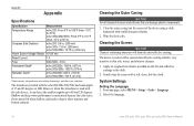
..., bottom type, and other water conditions. Wipe the device dry. System Settings Setting the Language 1. Select the language. 18 echo 200, echo 300c, echo 500c, and echo 550c Owner's Manual Clean the outer casing (not the screen) of 15 and 45 degrees at 3dB. The device is coated... coating which is used with the echo 200/300c/500/550c has beam angles of the device using a cloth dampened with a soft, clean, lint-free cloth. The transducer provided with the echo device, it can damage plastic components. 1. However, when this transducer is very sensitive to show structure and...
..., bottom type, and other water conditions. Wipe the device dry. System Settings Setting the Language 1. Select the language. 18 echo 200, echo 300c, echo 500c, and echo 550c Owner's Manual Clean the outer casing (not the screen) of 15 and 45 degrees at 3dB. The device is coated... coating which is used with the echo 200/300c/500/550c has beam angles of the device using a cloth dampened with a soft, clean, lint-free cloth. The transducer provided with the echo device, it can damage plastic components. 1. However, when this transducer is very sensitive to show structure and...

