Installation Guide
Page 1
GSD 20 Sounder Module installation instructions
GSD 20 Sounder Module installation instructions
Installation Guide
Page 3
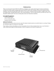
... are missing, please contact your new sonar. Included Equipment: • GSD 20 Sounder Module • 30' (9.1 m) Power/Data Cable • Installation Guide for complete sounder control from your local dealer or contact Garmin Product Support for choosing the Garmin GSD 20. The GSD 20 is an intelligent, remote sounder module designed to multiple head units, providing for the GSD 20 Optional Transducers The transducer acts as found...
... are missing, please contact your new sonar. Included Equipment: • GSD 20 Sounder Module • 30' (9.1 m) Power/Data Cable • Installation Guide for complete sounder control from your local dealer or contact Garmin Product Support for choosing the Garmin GSD 20. The GSD 20 is an intelligent, remote sounder module designed to multiple head units, providing for the GSD 20 Optional Transducers The transducer acts as found...
Installation Guide
Page 5
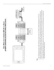
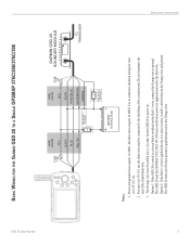
... for wiring the GPS 17 sensor and other wires require 22 AWG. Do not terminate the end of the extension run. When multiple GPSMAP 3005C/3006C/3010C units are in use, only wire the GSD 20 to the Garmin Marnine Network. The GSD 20 information is transmitted ...ground wires require 18 AWG. GSD 20 Sonar Module BASIC WIRING FOR THE GARMIN GSD 20 TO A SINGLE GPSMAP 2006/2006C/2010/2010C/3005C/3006C/3010C FUSE 5 A WIRE COLOR RED BLACK ORANGE WHITE/BLUE WHITE/BROWN WIRE COLOR RED FUSE 2 A BLACK ORANGE WHITE/BLUE WHITE/BROWN GARMIN GSD 20 SOUNDER MODULE TO TRANSDUCER BATTERY 10-35 VOLTS...
... for wiring the GPS 17 sensor and other wires require 22 AWG. Do not terminate the end of the extension run. When multiple GPSMAP 3005C/3006C/3010C units are in use, only wire the GSD 20 to the Garmin Marnine Network. The GSD 20 information is transmitted ...ground wires require 18 AWG. GSD 20 Sonar Module BASIC WIRING FOR THE GARMIN GSD 20 TO A SINGLE GPSMAP 2006/2006C/2010/2010C/3005C/3006C/3010C FUSE 5 A WIRE COLOR RED BLACK ORANGE WHITE/BLUE WHITE/BROWN WIRE COLOR RED FUSE 2 A BLACK ORANGE WHITE/BLUE WHITE/BROWN GARMIN GSD 20 SOUNDER MODULE TO TRANSDUCER BATTERY 10-35 VOLTS...
Installation Guide
Page 7
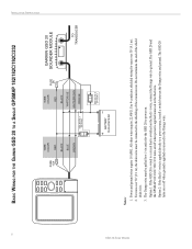
...GSD 20 Sonar Module BASIC WIRING FOR THE GARMIN GSD 20 TO A SINGLE GPSMAP 276C/296/376C/396 INSTALLATION INSTRUCTIONS ON OFF FUSE 1.5A WIRE COLOR RED BLACK BLUE YELLOW SEE NOTE 3 ON OPTION 1 OFF WIRE COLOR RED FUSE 2A BLACK WHITE/BLUE WHITE/BROWN ORANGE BATTERY 10-35 VOLTS DC SEE NOTE 3 OPTION 2 GARMIN GSD 20 SOUNDER MODULE... TO TRANSDUCER Notes: 1. The GSD 20 and the GPSMAP 276C/296/376C/396 turn on /off when power is applied/removed to a power ...
...GSD 20 Sonar Module BASIC WIRING FOR THE GARMIN GSD 20 TO A SINGLE GPSMAP 276C/296/376C/396 INSTALLATION INSTRUCTIONS ON OFF FUSE 1.5A WIRE COLOR RED BLACK BLUE YELLOW SEE NOTE 3 ON OPTION 1 OFF WIRE COLOR RED FUSE 2A BLACK WHITE/BLUE WHITE/BROWN ORANGE BATTERY 10-35 VOLTS DC SEE NOTE 3 OPTION 2 GARMIN GSD 20 SOUNDER MODULE... TO TRANSDUCER Notes: 1. The GSD 20 and the GPSMAP 276C/296/376C/396 turn on /off when power is applied/removed to a power ...
Installation Guide
Page 8
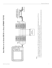
...6 GSD 20 Sonar Module BASIC WIRING FOR THE GARMIN GSD 20 TO A SINGLE GPSMAP 182/182C/192C/232 FUSE 1.5A WIRE COLOR RED BLACK BLUE BROWN SEE NOTE 3 ON OPTION 1 OFF WIRE COLOR RED FUSE 2A BLACK WHITE/BLUE WHITE/BROWN ORANGE BATTERY 10-35 VOLTS DC SEE NOTE 3 OPTION 2 GARMIN GSD 20 SOUNDER MODULE TO ...TRANSDUCER Notes: 1. Power and ground wires require 18 AWG. Do not terminate the end of the extension run. Option 1: If the GSD 20 is wired to a circuit that is applied/removed to the ...
...6 GSD 20 Sonar Module BASIC WIRING FOR THE GARMIN GSD 20 TO A SINGLE GPSMAP 182/182C/192C/232 FUSE 1.5A WIRE COLOR RED BLACK BLUE BROWN SEE NOTE 3 ON OPTION 1 OFF WIRE COLOR RED FUSE 2A BLACK WHITE/BLUE WHITE/BROWN ORANGE BATTERY 10-35 VOLTS DC SEE NOTE 3 OPTION 2 GARMIN GSD 20 SOUNDER MODULE TO ...TRANSDUCER Notes: 1. Power and ground wires require 18 AWG. Do not terminate the end of the extension run. Option 1: If the GSD 20 is wired to a circuit that is applied/removed to the ...
Installation Guide
Page 9
Use 4-conductor, shielded wiring for wiring the GPS 17 sensor and other wires require 22 AWG. Refer to the GPSMAP 172/172C Owner's Manual for runs over 30' (9.1 m), the drain wire must be connected to .... 3. INSTALLATION INSTRUCTIONS 7 Power and ground wires require 18 AWG. For runs over 30' (9.1 m). 2. GSD 20 Sonar Module BASIC WIRING FOR THE GARMIN GSD 20 TO A SINGLE GPSMAP 172/172C FUSE 5A WIRE COLOR RED BLACK BLUE BROWN ORANGE WIRE COLOR RED FUSE 2A BLACK WHITE/BLUE WHITE/BROWN ORANGE GARMIN GSD 20 SOUNDER MODULE TO TRANSDUCER BATTERY 10-35 VOLTS DC Notes: 1.
Use 4-conductor, shielded wiring for wiring the GPS 17 sensor and other wires require 22 AWG. Refer to the GPSMAP 172/172C Owner's Manual for runs over 30' (9.1 m), the drain wire must be connected to .... 3. INSTALLATION INSTRUCTIONS 7 Power and ground wires require 18 AWG. For runs over 30' (9.1 m). 2. GSD 20 Sonar Module BASIC WIRING FOR THE GARMIN GSD 20 TO A SINGLE GPSMAP 172/172C FUSE 5A WIRE COLOR RED BLACK BLUE BROWN ORANGE WIRE COLOR RED FUSE 2A BLACK WHITE/BLUE WHITE/BROWN ORANGE GARMIN GSD 20 SOUNDER MODULE TO TRANSDUCER BATTERY 10-35 VOLTS DC Notes: 1.
Installation Guide
Page 11
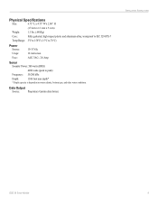
...) Frequency: 50/200 kHz Depth: 1500 foot max depth* * Depth capacity is dependent on water salinity, bottom type, and other water conditions. INSTALLATION INSTRUCTIONS GSD 20 Sonar Module 9 AGC/3AG - 2.0 Amp Sonar Sounder Power: 500 watts (RMS) 4000 watts (peak to 70°C) Power Source: Usage: Fuse: 10-35 Vdc 18 watts max. Data Output Source...
...) Frequency: 50/200 kHz Depth: 1500 foot max depth* * Depth capacity is dependent on water salinity, bottom type, and other water conditions. INSTALLATION INSTRUCTIONS GSD 20 Sonar Module 9 AGC/3AG - 2.0 Amp Sonar Sounder Power: 500 watts (RMS) 4000 watts (peak to 70°C) Power Source: Usage: Fuse: 10-35 Vdc 18 watts max. Data Output Source...


