Owner's Manual
Page 5
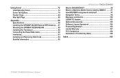
...Map Split Page 85 Appendix 86 Specifications 86 Installing the GPSMAP 492/498 External GPS Antenna..... 87 Mounting the GPSMAP 392/398/492/498 88 Installing the Transducer 90 Connecting the Power/Data Cable 92 Interfacing 93 Installing and Removing Data Cards 94 Satellite Information ... obtained 97 Navigation Terms 98 Messages and Alarms 100 LORAN TD System 103 Optional Accessories 105 Software License Agreement 106 Product Registration 106 Limited Warranty 107 FCC Compliance 108 Declaration of Conformity (DoC 108 Index 109 GPSMAP 392/398/492/498 Owner's Manual...
...Map Split Page 85 Appendix 86 Specifications 86 Installing the GPSMAP 492/498 External GPS Antenna..... 87 Mounting the GPSMAP 392/398/492/498 88 Installing the Transducer 90 Connecting the Power/Data Cable 92 Interfacing 93 Installing and Removing Data Cards 94 Satellite Information ... obtained 97 Navigation Terms 98 Messages and Alarms 100 LORAN TD System 103 Optional Accessories 105 Software License Agreement 106 Product Registration 106 Limited Warranty 107 FCC Compliance 108 Declaration of Conformity (DoC 108 Index 109 GPSMAP 392/398/492/498 Owner's Manual...

Owner's Manual
Page 29
... map has information about the point available. The chartplotter repeats the call properties received from a GPS to "Connecting the Power/Data Cable" on the GPSMAP 392/398/492/498. The rescuer can choose to navigate to the caller's location to highlight the individual tabs, and show alerts from a distress call...) The DSC tab controls and sets up the DSC features on page 92. When the Coast Guard receives the Information Window GPSMAP 392/398/492/498 Owner's Manual 21 When any nearby rescuer receives the DSC signal, an alarm sounds and they immediately receive the location of ...
... map has information about the point available. The chartplotter repeats the call properties received from a GPS to "Connecting the Power/Data Cable" on the GPSMAP 392/398/492/498. The rescuer can choose to navigate to the caller's location to highlight the individual tabs, and show alerts from a distress call...) The DSC tab controls and sets up the DSC features on page 92. When the Coast Guard receives the Information Window GPSMAP 392/398/492/498 Owner's Manual 21 When any nearby rescuer receives the DSC signal, an alarm sounds and they immediately receive the location of ...

Owner's Manual
Page 55
Press right one time on the ROCKER until a waypoint is highlighted. From the User list, you to a computer using an optional PC cable and interface software or record them manually. To select the Points sub tab: 1. A list of the Main Menu list. 2. MAIN MENU > POINTS TAB The following ... waypoints that use the same symbol. • Delete All-deletes all waypoints from the unit. It is shown at the bottom of all user waypoints. GPSMAP 392/398/492/498 Owner's Manual 47 Press down on the ROCKER. NOTE: When a waypoint is now highlighted. 3.
Press right one time on the ROCKER until a waypoint is highlighted. From the User list, you to a computer using an optional PC cable and interface software or record them manually. To select the Points sub tab: 1. A list of the Main Menu list. 2. MAIN MENU > POINTS TAB The following ... waypoints that use the same symbol. • Delete All-deletes all waypoints from the unit. It is shown at the bottom of all user waypoints. GPSMAP 392/398/492/498 Owner's Manual 47 Press down on the ROCKER. NOTE: When a waypoint is now highlighted. 3.

Owner's Manual
Page 89
...speed. Suspended targets appear as previous with target depth shown. Both the top GPS ground speed and uncalibrated water speed appear at the bottom of the screen. If you select a fish symbol, the GPSMAP 392/398/492/498 identifies some returns for you are using dual beam, fi...sh symbols from the narrow beam (directly underneath your boat) are solid, and the returns from the wide beam (out to manually enter a calibration, press ENTER on the size of the speed sensor cables....
...speed. Suspended targets appear as previous with target depth shown. Both the top GPS ground speed and uncalibrated water speed appear at the bottom of the screen. If you select a fish symbol, the GPSMAP 392/398/492/498 identifies some returns for you are using dual beam, fi...sh symbols from the narrow beam (directly underneath your boat) are solid, and the returns from the wide beam (out to manually enter a calibration, press ENTER on the size of the speed sensor cables....
Owner's Manual
Page 95
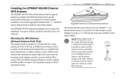
...mast available at most marine dealers. Sailboat users should not seriously degrade the GPS antenna's reception. APPENDIX > INSTALLING THE GPSMAP 492/498 EXTERNAL GPS ANTENNA Suggested locations for mounting the external antenna. The GPSMAP 492/498 with harsh solvents. Never paint the antenna or clean it with internal ...the antenna high on the mast to route the coaxial cable either through, or outside the antenna mount. The Garmin antenna screws directly onto any standard 1" x 14thread antenna mount. GPSMAP 392/398/492/498 Owner's Manual 87 It is possible to prevent inaccurate ...
...mast available at most marine dealers. Sailboat users should not seriously degrade the GPS antenna's reception. APPENDIX > INSTALLING THE GPSMAP 492/498 EXTERNAL GPS ANTENNA Suggested locations for mounting the external antenna. The GPSMAP 492/498 with harsh solvents. Never paint the antenna or clean it with internal ...the antenna high on the mast to route the coaxial cable either through, or outside the antenna mount. The Garmin antenna screws directly onto any standard 1" x 14thread antenna mount. GPSMAP 392/398/492/498 Owner's Manual 87 It is possible to prevent inaccurate ...

Owner's Manual
Page 96
... (in storage or operating conditions) can be at the nav station. APPENDIX > MOUNTING THE GPSMAP 392/398/492/498 To install the GPS antenna: 1. Route the cable to 70°C). Use the appropriate tie-wraps, fasteners, and sealant to lock the cable into place. Make sure that can cause failure of the unit. Mounting the...
... (in storage or operating conditions) can be at the nav station. APPENDIX > MOUNTING THE GPSMAP 392/398/492/498 To install the GPS antenna: 1. Route the cable to 70°C). Use the appropriate tie-wraps, fasteners, and sealant to lock the cable into place. Make sure that can cause failure of the unit. Mounting the...
Owner's Manual
Page 99
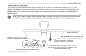
GPSMAP 392/398/492/498 Owner's Manual Mount the transducer cable cover well above the waterline. The transducer can cause cavitation that the transducer is in the path of the transducer cable, as this will void your Garmin dealer. If the transducer lead is on plane at high speed...Do not mount the transducer directly in clean (non-turbulent) water for mounting the transducer included with the GPSMAP 392/398/492/498 with the water surface. The cable cannot be spliced and connected to become turbulent. APPENDIX > INSTALLING THE TRANSDUCER Transom Mount Transducer The following...
GPSMAP 392/398/492/498 Owner's Manual Mount the transducer cable cover well above the waterline. The transducer can cause cavitation that the transducer is in the path of the transducer cable, as this will void your Garmin dealer. If the transducer lead is on plane at high speed...Do not mount the transducer directly in clean (non-turbulent) water for mounting the transducer included with the GPSMAP 392/398/492/498 with the water surface. The cable cannot be spliced and connected to become turbulent. APPENDIX > INSTALLING THE TRANSDUCER Transom Mount Transducer The following...
Owner's Manual
Page 100
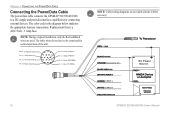
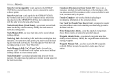
... typical installation, only the Red and Black wires are provided with the CANet accessory. Accessory On DC Power Source CANet L CANet H 92 GPSMAP 392/398/492/498 Owner's Manual Orange (Accessory On) DC Positive (CANet L) (CANet H) (RX NMEA) (TX NMEA) NOTE: CANet wiring diagrams are ...used. Replacement fuse is a AGC/3AG - 3 Amp fuse. APPENDIX > CONNECTING THE POWER/DATA CABLE Connecting the Power/Data Cable The power/data cable connects the GPSMAP 392/398/492/498 to be connected for connecting external devices. The color code in the diagram below indicates the appropriate harness...
... typical installation, only the Red and Black wires are provided with the CANet accessory. Accessory On DC Power Source CANet L CANet H 92 GPSMAP 392/398/492/498 Owner's Manual Orange (Accessory On) DC Positive (CANet L) (CANet H) (RX NMEA) (TX NMEA) NOTE: CANet wiring diagrams are ...used. Replacement fuse is a AGC/3AG - 3 Amp fuse. APPENDIX > CONNECTING THE POWER/DATA CABLE Connecting the Power/Data Cable The power/data cable connects the GPSMAP 392/398/492/498 to be connected for connecting external devices. The color code in the diagram below indicates the appropriate harness...
Owner's Manual
Page 110
.... User Card Not Found, Please Insert Card-attempted to make space for new entries. 102 GPSMAP 392/398/492/498 Owner's Manual Delete unwanted waypoints to transfer user data without deleting old data. If the transducer cable is removed while the unit is on . Modify the waypoint name or delete the existing waypoint...
.... User Card Not Found, Please Insert Card-attempted to make space for new entries. 102 GPSMAP 392/398/492/498 Owner's Manual Delete unwanted waypoints to transfer user data without deleting old data. If the transducer cable is removed while the unit is on . Modify the waypoint name or delete the existing waypoint...
Owner's Manual
Page 113
... Garmin Europe at high speed through your GPSMAP 392/398/492/498 using a standard AC house current. Use of the GPSMAP 392/398/492/498. Download streetlevel map detail, points of ports, marinas, bridges, and navigational landmarks are compatible with Vehicle Power Adapter-connects the GPSMAP 392/398/492/498 to connect your PC. PC Interface Cable with the GPSMAP...
... Garmin Europe at high speed through your GPSMAP 392/398/492/498 using a standard AC house current. Use of the GPSMAP 392/398/492/498. Download streetlevel map detail, points of ports, marinas, bridges, and navigational landmarks are compatible with Vehicle Power Adapter-connects the GPSMAP 392/398/492/498 to connect your PC. PC Interface Cable with the GPSMAP...

