Technical Reference for Garmin NMEA 2000 Products
Page 3
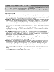
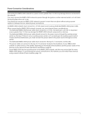
...Cable: A cable connecting an NMEA 2000 device to the NMEA 2000 network. Power to the NMEA 2000 network should use when calculating the power needs and balance of the NMEA 2000 backbone. Backbone Cable: Backbone cables extend the NMEA 2000 backbone to connect NMEA 2000 devices located in different places... ft.) maximum length. Item Not pictured Description Field-installable connector Garmin Part Number Notes 010-11094-00: male 010-11095-00: female Can be used in place of a male terminator (not available as three T-connectors connected side to side with one male and two female ...
...Cable: A cable connecting an NMEA 2000 device to the NMEA 2000 network. Power to the NMEA 2000 network should use when calculating the power needs and balance of the NMEA 2000 backbone. Backbone Cable: Backbone cables extend the NMEA 2000 backbone to connect NMEA 2000 devices located in different places... ft.) maximum length. Item Not pictured Description Field-installable connector Garmin Part Number Notes 010-11094-00: male 010-11095-00: female Can be used in place of a male terminator (not available as three T-connectors connected side to side with one male and two female ...
Technical Reference for Garmin NMEA 2000 Products
Page 5
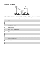
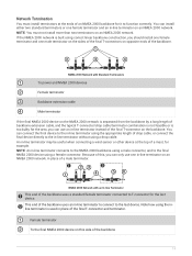
... NMEA 2000 network, and others may require a separate power connection. Consult the installation instructions for each device or sensor on the network. Wind sensor Chartplotter or multifunction device (MFD) Antenna (GPS or satellite) Marine instrument Ignition or in-line switch and fuse 12 Vdc power source Drop cable Female terminator Backbone extension cable T-connector Male terminator 5 Sample NMEA 2000 Network NOTE...
... NMEA 2000 network, and others may require a separate power connection. Consult the installation instructions for each device or sensor on the network. Wind sensor Chartplotter or multifunction device (MFD) Antenna (GPS or satellite) Marine instrument Ignition or in-line switch and fuse 12 Vdc power source Drop cable Female terminator Backbone extension cable T-connector Male terminator 5 Sample NMEA 2000 Network NOTE...
Technical Reference for Garmin NMEA 2000 Products
Page 6
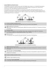
... is used to connect a device or power to the network only, and the backbone cannot route through a backbone cable extension. NMEA 2000 Network with Correct Linear Backbone Construction Female terminator installed correctly The terminator must connect to one another using a cable connected to the...connect to the side of the last T-connector in the backbone, and cannot connect to the side of the last T-connector in the backbone. Male terminator installed incorrectly The terminator must connect to the top of one another either directly or through the top of T-connectors and cables...
... is used to connect a device or power to the network only, and the backbone cannot route through a backbone cable extension. NMEA 2000 Network with Correct Linear Backbone Construction Female terminator installed correctly The terminator must connect to one another using a cable connected to the...connect to the side of the last T-connector in the backbone, and cannot connect to the side of the last T-connector in the backbone. Male terminator installed incorrectly The terminator must connect to the top of one another either directly or through the top of T-connectors and cables...
Technical Reference for Garmin NMEA 2000 Products
Page 7
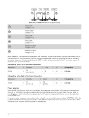
... length of the backbone and the power needs of a T-connector, not the side. • The power cable can install these considerations: • The dedicated NMEA 2000 power cable must connect to the top of the devices on either end or in use. An NMEA 2000 network must connect the NMEA 2000 network to a 12 Vdc power source using a power isolator (Power Isolation, page 10). 7
... length of the backbone and the power needs of a T-connector, not the side. • The power cable can install these considerations: • The dedicated NMEA 2000 power cable must connect to the top of the devices on either end or in use. An NMEA 2000 network must connect the NMEA 2000 network to a 12 Vdc power source using a power isolator (Power Isolation, page 10). 7

Technical Reference for Garmin NMEA 2000 Products
Page 8
... and the power needs of the devices on the network load and distance from the = (ohms/m) Garmin cable resistance × power connection to the furthest device (in the network depends on the network. For the NMEA 2000 network to work properly there must connect power to cable resistance (ohms/m). When evaluating the results of your NMEA 2000 network, use this Tconnector. Power Distribution...
... and the power needs of the devices on the network load and distance from the = (ohms/m) Garmin cable resistance × power connection to the furthest device (in the network depends on the network. For the NMEA 2000 network to work properly there must connect power to cable resistance (ohms/m). When evaluating the results of your NMEA 2000 network, use this Tconnector. Power Distribution...
Technical Reference for Garmin NMEA 2000 Products
Page 10
... = 10 m Backbone cable Length = 6 m When the NMEA 2000 network is connected directly to another Tconnector (as a boat engine, provide power to the NMEA 2000 network. If the T-connector to which you can install a power isolator (010-11580-00) in the backbone to when connecting devices to the network that T-connector as part of the Power Connection Resistance × Distance × Load...
... = 10 m Backbone cable Length = 6 m When the NMEA 2000 network is connected directly to another Tconnector (as a boat engine, provide power to the NMEA 2000 network. If the T-connector to which you can install a power isolator (010-11580-00) in the backbone to when connecting devices to the network that T-connector as part of the Power Connection Resistance × Distance × Load...
Technical Reference for Garmin NMEA 2000 Products
Page 11
... backbone uses an in place of the final T-connector and terminator. Network Termination You must not install more than two terminators on opposite ends of the backbone. NMEA 2000 Network with Standard Terminators To power and NMEA 2000 devices Female terminator Backbone extension cable Male ... uses a standard female terminator connected to T-connector for it to the final NMEA 2000 device using a male connector, and to function correctly. NMEA 2000 Network with an In-line Terminator This end of drop cable, or connect the final device directly to the in -line terminator connects ...
... backbone uses an in place of the final T-connector and terminator. Network Termination You must not install more than two terminators on opposite ends of the backbone. NMEA 2000 Network with Standard Terminators To power and NMEA 2000 devices Female terminator Backbone extension cable Male ... uses a standard female terminator connected to T-connector for it to the final NMEA 2000 device using a male connector, and to function correctly. NMEA 2000 Network with an In-line Terminator This end of drop cable, or connect the final device directly to the in -line terminator connects ...
Technical Reference for Garmin NMEA 2000 Products
Page 12
... length of sensors may use a converter or adapter to connect a Garmin NMEA 2000 device to an NMEA 2000 network if it is necessary or a specific combination of all cables and connectors. You must not add more terminators to a backbone with mini connectors. General NMEA 2000 Data Types Every NMEA 2000 certified sensor provides unique information to NMEA 2000 certified...
... length of sensors may use a converter or adapter to connect a Garmin NMEA 2000 device to an NMEA 2000 network if it is necessary or a specific combination of all cables and connectors. You must not add more terminators to a backbone with mini connectors. General NMEA 2000 Data Types Every NMEA 2000 certified sensor provides unique information to NMEA 2000 certified...
Installation Instructions
Page 1
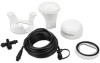
... all installation instructions before proceeding. GPS 24XD NMEA 2000® INSTALLATION INSTRUCTIONS Important Safety Information CAUTION To avoid possible personal injury, always wear safety goggles, ear protection, and a dust mask when drilling, cutting, or sanding. Use the appropriate fasteners, tools, and mounts listed, which are available at most marine dealers. For the best performance and to avoid damage to install one. Install the...
... all installation instructions before proceeding. GPS 24XD NMEA 2000® INSTALLATION INSTRUCTIONS Important Safety Information CAUTION To avoid possible personal injury, always wear safety goggles, ear protection, and a dust mask when drilling, cutting, or sanding. Use the appropriate fasteners, tools, and mounts listed, which are available at most marine dealers. For the best performance and to avoid damage to install one. Install the...

Installation Instructions
Page 2
... with the antenna. If necessary, the antenna may be on a flat surface or attach it where you use mounting hardware other sources of the radar . A strong magnetic field can route the cable outside of the radar . 2 You can damage the antenna. For best performance, consider these guidelines when selecting the antenna mounting location. • To ensure the best reception, the antenna should be mounted in...
... with the antenna. If necessary, the antenna may be on a flat surface or attach it where you use mounting hardware other sources of the radar . A strong magnetic field can route the cable outside of the radar . 2 You can damage the antenna. For best performance, consider these guidelines when selecting the antenna mounting location. • To ensure the best reception, the antenna should be mounted in...
Installation Instructions
Page 3
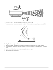
• The antenna should not be mounted within 1 m (3 ft.) of a VHF radio antenna or the path of a radar . Testing the Mounting Location 1 Temporarily secure the antenna in the path of the radar . • The antenna should not be mounted directly in the preferred mounting location and test it for correct operation. 2 If you experience interference with other electronics, move the antenna to a different location, and test it again. 3 Repeat steps 1-2 until you observe full or acceptable signal strength. 4 Permanently mount the antenna. 3
• The antenna should not be mounted within 1 m (3 ft.) of a VHF radio antenna or the path of a radar . Testing the Mounting Location 1 Temporarily secure the antenna in the path of the radar . • The antenna should not be mounted directly in the preferred mounting location and test it for correct operation. 2 If you experience interference with other electronics, move the antenna to a different location, and test it again. 3 Repeat steps 1-2 until you observe full or acceptable signal strength. 4 Permanently mount the antenna. 3
Installation Instructions
Page 4
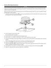
.... 4 If the included M4 screws are too short, use a countersink bit to the mounting bracket . 9 Route the cable away from sources of the bracket. 2 Set the surface-mount bracket aside. Surface Mounting the Antenna NOTICE If you must test the mounting location for correct operation (Testing the Mounting Location, page 3). 1 Using the surface-mount bracket as your mounting template, mark the three pilot-hole locations and trace...
.... 4 If the included M4 screws are too short, use a countersink bit to the mounting bracket . 9 Route the cable away from sources of the bracket. 2 Set the surface-mount bracket aside. Surface Mounting the Antenna NOTICE If you must test the mounting location for correct operation (Testing the Mounting Location, page 3). 1 Using the surface-mount bracket as your mounting template, mark the three pilot-hole locations and trace...
Installation Instructions
Page 5
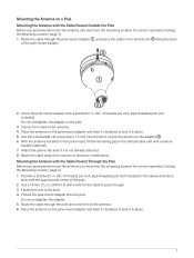
... place. 5 Use the included M3 set screw and a 1.5 mm hex wrench to secure the antenna to the adapter . 6 With the antenna installed on the pole-mount adapter and twist it clockwise to drill a hole for correct operation (Testing the Mounting Location, page 3). 1 Route the cable through the pole-mount adapter , and place the cable in the vertical slot along the base of electronic interference. Mounting the Antenna with a marine...
... place. 5 Use the included M3 set screw and a 1.5 mm hex wrench to secure the antenna to the adapter . 6 With the antenna installed on the pole-mount adapter and twist it clockwise to drill a hole for correct operation (Testing the Mounting Location, page 3). 1 Route the cable through the pole-mount adapter , and place the cable in the vertical slot along the base of electronic interference. Mounting the Antenna with a marine...
Installation Instructions
Page 6
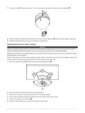
7 Use the included M3 set screw and a 1.5 mm hex wrench to secure the antenna to the adapter . 8 With the antenna installed on the under-deck mounting bracket . 2 Place the antenna in the under-deck mounting bracket. 3 Adhere the under-deck mounting bracket to the mounting surface. 4 Secure the under-deck mounting bracket to the mounting surface with a marine sealant (optional). 9 Route the cable away from sources of electronic interference. Mounting the Antenna Under...
7 Use the included M3 set screw and a 1.5 mm hex wrench to secure the antenna to the adapter . 8 With the antenna installed on the under-deck mounting bracket . 2 Place the antenna in the under-deck mounting bracket. 3 Adhere the under-deck mounting bracket to the mounting surface. 4 Secure the under-deck mounting bracket to the mounting surface with a marine sealant (optional). 9 Route the cable away from sources of electronic interference. Mounting the Antenna Under...
Installation Instructions
Page 7
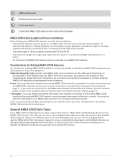
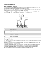
... heading alignment to receive magnetic heading data. Connecting the Antenna NMEA 2000 Network Connection If you do not have an existing NMEA 2000 network, you must install a NMEA 2000 network on NMEA 2000, go to garmin.com/manuals/nmea_2000. For more cable is packaged with a third-party device, you can be installed if desired. GPS 24xd antenna NMEA 2000 drop cable NMEA 2000...
... heading alignment to receive magnetic heading data. Connecting the Antenna NMEA 2000 Network Connection If you do not have an existing NMEA 2000 network, you must install a NMEA 2000 network on NMEA 2000, go to garmin.com/manuals/nmea_2000. For more cable is packaged with a third-party device, you can be installed if desired. GPS 24xd antenna NMEA 2000 drop cable NMEA 2000...
Installation Instructions
Page 8
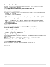
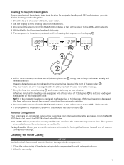
... network as possible. setting. The device still outputs GPS Course over Ground. NOTE: The antenna compass must connect the antenna to keep the boat as steady and level as a compatible Garmin chartplotter. 1 Select Menu > Settings > Communications > NMEA 2000 Setup > Device List. 2 Select the GPS 24xd NMEA 2000 from the device list. 3 Select Review > Compass Cal. > Begin. 4 Follow the on -screen instructions until the magnetic...
... network as possible. setting. The device still outputs GPS Course over Ground. NOTE: The antenna compass must connect the antenna to keep the boat as steady and level as a compatible Garmin chartplotter. 1 Select Menu > Settings > Communications > NMEA 2000 Setup > Device List. 2 Select the GPS 24xd NMEA 2000 from the device list. 3 Select Review > Compass Cal. > Begin. 4 Follow the on -screen instructions until the magnetic...
Installation Instructions
Page 9
... antenna. NOTE: The boat must be able to keep the boat as steady and level as possible. The boat should not list during calibration. NOTE: You must remove from the NMEA 2000 network on the display . You may receive an error message that the heading was lost. Before you must not use GPS Course Over Ground...
... antenna. NOTE: The boat must be able to keep the boat as steady and level as possible. The boat should not list during calibration. NOTE: You must remove from the NMEA 2000 network on the display . You may receive an error message that the heading was lost. Before you must not use GPS Course Over Ground...
Installation Instructions
Page 11
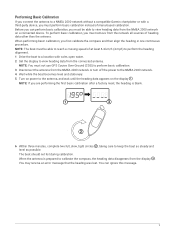
...of the device using a cloth dampened with a fixed value of the procedure . From the NMEA 2000 device list, select the GPS 24xd, and select Review. This option is pre-configured, but you may customize your antenna configuration as possible. You will be disabled on the next power cycle. After... reset the antenna settings to the factory default value. NOTE: If the magnetic heading is displayed, the fixed value is displayed, the fixed value may receive an error message that the antenna has detected the start of 123 degrees to indicate heading will lose all custom configuration settings....
...of the device using a cloth dampened with a fixed value of the procedure . From the NMEA 2000 device list, select the GPS 24xd, and select Review. This option is pre-configured, but you may customize your antenna configuration as possible. You will be disabled on the next power cycle. After... reset the antenna settings to the factory default value. NOTE: If the magnetic heading is displayed, the fixed value is displayed, the fixed value may receive an error message that the antenna has detected the start of 123 degrees to indicate heading will lose all custom configuration settings....
Installation Instructions
Page 12
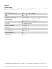
... @ 12 Vdc 150 mA @ 12 Vdc 3 150 mA 1 The device withstands incidental exposure to water of up to 1 m for up to www.garmin.com/waterrating. 12 For instructions on updating the software, see your chartplotter owner's manual at support.garmin.com. Specifications Dimensions (diameter x height) Weight NMEA 2000 drop cable length Temperature range Case material Water rating Compass-safe distance Input voltage Max.
... @ 12 Vdc 150 mA @ 12 Vdc 3 150 mA 1 The device withstands incidental exposure to water of up to 1 m for up to www.garmin.com/waterrating. 12 For instructions on updating the software, see your chartplotter owner's manual at support.garmin.com. Specifications Dimensions (diameter x height) Weight NMEA 2000 drop cable length Temperature range Case material Water rating Compass-safe distance Input voltage Max.

Installation Instructions
Page 14
... a Class B digital device, pursuant to part 15 of acceptable quality and the failure does not amount to radio communications if not installed and used in a residential installation. Repairs should only be determined by turning the equipment off and on a circuit different from that may cause undesired operation. You are in relation to radio or television reception, which the receiver is connected. • Consult...
... a Class B digital device, pursuant to part 15 of acceptable quality and the failure does not amount to radio communications if not installed and used in a residential installation. Repairs should only be determined by turning the equipment off and on a circuit different from that may cause undesired operation. You are in relation to radio or television reception, which the receiver is connected. • Consult...


