
Flush Mount Template
Page 1
... large templates, you print a mounting template on the mounting surface of your own. Printing a Mounting Template Notice It is not recommended that you need large enough paper and printer. Notice Garmin is larger than the template. If you do print the template, you must follow these instructions. Failure to have the correct sized...➊. 3 Ensure the check mark is next to Auto-Rotate and Center ➋. 4 Drag the arrow ➌ to the right, to follow these instructions, may result in the product box. Use the template that the paper size is not responsible for printing...
... large templates, you print a mounting template on the mounting surface of your own. Printing a Mounting Template Notice It is not recommended that you need large enough paper and printer. Notice Garmin is larger than the template. If you do print the template, you must follow these instructions. Failure to have the correct sized...➊. 3 Ensure the check mark is next to Auto-Rotate and Center ➋. 4 Drag the arrow ➌ to the right, to follow these instructions, may result in the product box. Use the template that the paper size is not responsible for printing...

Flush Mount Template
Page 2
GMR® 400/600/1200/2500 Series Mounting Template 180° forskydning 180°-forskyvning 180° förskjutning Décalage = 0° Scostamento 0° Versatz von 0° Variación de 0° 180° .... (200 mm) Printed in . (140 mm) Décalage = 180° Scostamento 180° Versatz von 180° Variación de 180° © 2009-15 Garmin Ltd.
GMR® 400/600/1200/2500 Series Mounting Template 180° forskydning 180°-forskyvning 180° förskjutning Décalage = 0° Scostamento 0° Versatz von 0° Variación de 0° 180° .... (200 mm) Printed in . (140 mm) Décalage = 180° Scostamento 180° Versatz von 180° Variación de 180° © 2009-15 Garmin Ltd.

Important Safety and Product Information
Page 2
... that are valuable trade secrets of Garmin and/or its maximum output power mode and when used in the normal operation of GNSS signals. Such repairs or replacement will not occur in the area of...use the software embedded in this device must accept any interference received, including interference that may experience degraded performance if you submit a claim for any user-serviceable parts. Before seeking warranty service, please access and review the online help . Marine Warranty Policy: Certain Garmin Marine products in the original country of purchase or follow the instructions...
... that are valuable trade secrets of Garmin and/or its maximum output power mode and when used in the normal operation of GNSS signals. Such repairs or replacement will not occur in the area of...use the software embedded in this device must accept any interference received, including interference that may experience degraded performance if you submit a claim for any user-serviceable parts. Before seeking warranty service, please access and review the online help . Marine Warranty Policy: Certain Garmin Marine products in the original country of purchase or follow the instructions...
Installation Instructions
Page 1
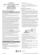
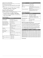
.... When connecting the power cable, do not look directly at the antenna at support.garmin.com. For instructions on updating the software, see your chartplotter owner's manual at close range when the radar is transmitting. Software Update You must be in the product specifications. • Other electronics and cables should be mounted more than a Garmin authorized service technician will not be mounted high above head...
.... When connecting the power cable, do not look directly at the antenna at support.garmin.com. For instructions on updating the software, see your chartplotter owner's manual at close range when the radar is transmitting. Software Update You must be in the product specifications. • Other electronics and cables should be mounted more than a Garmin authorized service technician will not be mounted high above head...
Installation Instructions
Page 2
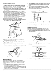
... the cables using a 5 mm hex wrench. Installing the Antenna Before you can install the antenna on the radar, you must securely mount the pedestal (Mounting the Radar...power and network cables through the holes. 3 From under the power and network connectors indicated on the template, drill a passthrough hole for Mounting, page 2). 1 Take note of which end of the threaded rods coated in .) drill bit, and route the cables through the surface (optional) (Wiring... the threaded rods using a 32 mm (11/4 in Petrolatum Primer into the mounting surface so they no longer turn easily. 2 Align...
... the cables using a 5 mm hex wrench. Installing the Antenna Before you can install the antenna on the radar, you must securely mount the pedestal (Mounting the Radar...power and network cables through the holes. 3 From under the power and network connectors indicated on the template, drill a passthrough hole for Mounting, page 2). 1 Take note of which end of the threaded rods coated in .) drill bit, and route the cables through the surface (optional) (Wiring... the threaded rods using a 32 mm (11/4 in Petrolatum Primer into the mounting surface so they no longer turn easily. 2 Align...
Installation Instructions
Page 3
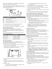
... install the power cable as close as indicated in the product specifications. Item Description To the Garmin Marine Network 10 A fuse holder Red (+) Black (-) To the boat battery (10 to 32 Vdc) 30 A fuse holder Water ground connection 1 Route the power cable to the radar and the voltage converter. 2 Use crimp connectors and heat-shrink tubing to connect the power cable to the 10 A fuse...
... install the power cable as close as indicated in the product specifications. Item Description To the Garmin Marine Network 10 A fuse holder Red (+) Black (-) To the boat battery (10 to 32 Vdc) 30 A fuse holder Water ground connection 1 Route the power cable to the radar and the voltage converter. 2 Use crimp connectors and heat-shrink tubing to connect the power cable to the 10 A fuse...
Installation Instructions
Page 4
... be used for Garmin Marine Network connections. ◦ Additional Garmin Marine Network cables and connectors are controlled with marine sealant. boat offset. Item Description To the Garmin Marine Network 15 A fuse holder To the boat battery (10 to 32 Vdc) Water ground connection 1 Route the power cable to the radar and boat battery. 2 Connect the power cable to the boat battery. 3 Connect the power cable to the POWER port on...
... be used for Garmin Marine Network connections. ◦ Additional Garmin Marine Network cables and connectors are controlled with marine sealant. boat offset. Item Description To the Garmin Marine Network 15 A fuse holder To the boat battery (10 to 32 Vdc) Water ground connection 1 Route the power cable to the radar and boat battery. 2 Connect the power cable to the boat battery. 3 Connect the power cable to the POWER port on...
Installation Instructions
Page 5
... rpm 80 kn GMR 420/620/1200 xHD2: From -15 to 70ºC (from 5 to 158ºF) GMR 2520 xHD2: From -15 to 60ºC (from the antenna at which radio frequency (RF) levels can be located in one radar mode is at 35°...position of -boat offset setting configured for use in a position on garmin.com. Specifications Specification Pedestal weight Antenna weight Power cable length Network cable length Antenna rotation speed Maximum wind load Temperature range Humidity Water rating Bearing accuracy Input voltage Fuse Input power GMR 424 and 426 Input power GMR 624 and 626 Measurement 21...
... rpm 80 kn GMR 420/620/1200 xHD2: From -15 to 70ºC (from 5 to 158ºF) GMR 2520 xHD2: From -15 to 60ºC (from the antenna at which radio frequency (RF) levels can be located in one radar mode is at 35°...position of -boat offset setting configured for use in a position on garmin.com. Specifications Specification Pedestal weight Antenna weight Power cable length Network cable length Antenna rotation speed Maximum wind load Temperature range Humidity Water rating Bearing accuracy Input voltage Fuse Input power GMR 424 and 426 Input power GMR 624 and 626 Measurement 21...
Installation Instructions
Page 6
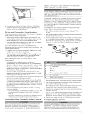
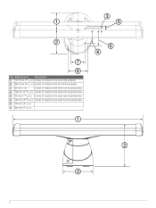
Center of rotation to the inner front mounting holes. Item Measurement Description 181.8 mm (7 3/16 in.) Center of rotation to the rear of the pedestal. 236.2 mm (9 5/16 in.) Center of rotation to the front of the pedestal. 25 mm (1 in.) Center of rotation to the inner rear mounting holes. 125 mm (4 15/16 in.) 50 mm (1 15/16 in.) 150 mm (5 29/32 in.) 140 mm (5 1/2 in.) 200 mm (7 7/8 in.) Center of rotation to the outer rear mounting holes. Center of rotation to the outer front mounting holes. 6
Center of rotation to the inner front mounting holes. Item Measurement Description 181.8 mm (7 3/16 in.) Center of rotation to the rear of the pedestal. 236.2 mm (9 5/16 in.) Center of rotation to the front of the pedestal. 25 mm (1 in.) Center of rotation to the inner rear mounting holes. 125 mm (4 15/16 in.) 50 mm (1 15/16 in.) 150 mm (5 29/32 in.) 140 mm (5 1/2 in.) 200 mm (7 7/8 in.) Center of rotation to the outer rear mounting holes. Center of rotation to the outer front mounting holes. 6
Installation Instructions
Page 7
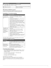
...; If a field-installable network connector was used without the express permission of Garmin. 7 Check the table provided in the Power Cable Extensions section of Garmin Ltd. Check the connector. Contact Garmin product support for help troubleshoot installation problems. Status LED Color Radar Status and Activity Solid red The radar is a trademark of these instructions to make sure the correct wire gauge is not...
...; If a field-installable network connector was used without the express permission of Garmin. 7 Check the table provided in the Power Cable Extensions section of Garmin Ltd. Check the connector. Contact Garmin product support for help troubleshoot installation problems. Status LED Color Radar Status and Activity Solid red The radar is a trademark of these instructions to make sure the correct wire gauge is not...


