
Installation Instructions
Page 1
... use of this radar conforms to the requirements of the body to install this device. For instructions on the opposite side of the radar beam before transmitting. GMR™ 18 HD3 AND 18/24 XHD3 INSTALLATION INSTRUCTIONS Important Safety Information WARNING See the Important Safety and Product Information guide in the product box for product warnings and other than a Garmin authorized service technician...
... use of this radar conforms to the requirements of the body to install this device. For instructions on the opposite side of the radar beam before transmitting. GMR™ 18 HD3 AND 18/24 XHD3 INSTALLATION INSTRUCTIONS Important Safety Information WARNING See the Important Safety and Product Information guide in the product box for product warnings and other than a Garmin authorized service technician...

Installation Instructions
Page 2
Tools Needed • Drill • 9.5 mm (3/8 in.) drill bit • 32 mm (1 1/4 in.) drill bit (optional) • 4 mm (5/32 in.) hex wrench • 13 mm (1/2 in.) wrench and torque wrench • Marine sealant 2
Tools Needed • Drill • 9.5 mm (3/8 in.) drill bit • 32 mm (1 1/4 in.) drill bit (optional) • 4 mm (5/32 in.) hex wrench • 13 mm (1/2 in.) wrench and torque wrench • Marine sealant 2

Installation Instructions
Page 3
...the second option is listed in the product specifications. • The radar must not mount the radar closer to people than the minimum safe distance value listed in a location where it can be connected to power and the Garmin network (Wiring and Connection Considerations, page 8). • ... radio frequency (RF) levels, you need to the waterline while at most marine dealers. These items are mounting the radar on a cabin roof, you may cause blind and shadow sectors, or generate false echoes. Use shims if necessary. • The radome has two mounting options when installed on...
...the second option is listed in the product specifications. • The radar must not mount the radar closer to people than the minimum safe distance value listed in a location where it can be connected to power and the Garmin network (Wiring and Connection Considerations, page 8). • ... radio frequency (RF) levels, you need to the waterline while at most marine dealers. These items are mounting the radar on a cabin roof, you may cause blind and shadow sectors, or generate false echoes. Use shims if necessary. • The radome has two mounting options when installed on...
Installation Instructions
Page 4
...compass, the radar should not be mounted closer to a compass than the compass-safe distance value listed in the product specifications. • Other electronics and cables should be mounted more than 2 m (6 ½ ft.) from the radar beam path. • GPS antennas should be either above or ...below the radar beam path. • The radar should be mounted at least 1 m (40 in.) from any transmitting equipment. • The radar should be mounted at least 1 m (40 in.) away from cables carrying radio signals such as VHF radios, cables, and antennas...
...compass, the radar should not be mounted closer to a compass than the compass-safe distance value listed in the product specifications. • Other electronics and cables should be mounted more than 2 m (6 ½ ft.) from the radar beam path. • GPS antennas should be either above or ...below the radar beam path. • The radar should be mounted at least 1 m (40 in.) from any transmitting equipment. • The radar should be mounted at least 1 m (40 in.) away from cables carrying radio signals such as VHF radios, cables, and antennas...

Installation Instructions
Page 5
... your boat, you should raise the dome so the beam clears the edge of the roof or hard top . 5 Roof Mounting Considerations NOTICE If you are mounting the radar on performance. If the surface is particularly important to avoid. The beam transmitted by this is metal, this radar ...spreads vertically 12.5 degrees from the horizontal mid line , and you may need to raise the installation height using a pedestal or other suitable ...
... your boat, you should raise the dome so the beam clears the edge of the roof or hard top . 5 Roof Mounting Considerations NOTICE If you are mounting the radar on performance. If the surface is particularly important to avoid. The beam transmitted by this is metal, this radar ...spreads vertically 12.5 degrees from the horizontal mid line , and you may need to raise the installation height using a pedestal or other suitable ...

Installation Instructions
Page 6
...install it high enough to avoid interference from the surface. 1 Based on the shape of the roof, complete an action: • Measure the distance from the intended mounting location to the furthest front corner of a rectangular roof . • Measure the distance from the intended mounting location to the front apex of a curved roof . 2 Use... this equation to determine the mounting height of the radar based on the distance you measured in the previous step:...
...install it high enough to avoid interference from the surface. 1 Based on the shape of the roof, complete an action: • Measure the distance from the intended mounting location to the furthest front corner of a rectangular roof . • Measure the distance from the intended mounting location to the front apex of a curved roof . 2 Use... this equation to determine the mounting height of the radar based on the distance you measured in the previous step:...

Installation Instructions
Page 7
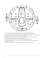
....), use the included mounting template to drill four 9.5 mm (3/8 in.) mounting holes. 2 Connect the power cable to the power port and the network cable to 1 3/16 in .) of the threaded rods may extend below the radome. 7 Apply a bead of marine sealant...cables into the mounting holes on the mounting surface around each mounting hole. 7 The cables should be used on mounting thicknesses of the radome. Mounting the Radar Before you mount the radar, you are not installing the device on a pre-drilled Garmin compatible radar mount, use longer threaded rods. 1 If you must review the mounting...
....), use the included mounting template to drill four 9.5 mm (3/8 in.) mounting holes. 2 Connect the power cable to the power port and the network cable to 1 3/16 in .) of the threaded rods may extend below the radome. 7 Apply a bead of marine sealant...cables into the mounting holes on the mounting surface around each mounting hole. 7 The cables should be used on mounting thicknesses of the radome. Mounting the Radar Before you mount the radar, you are not installing the device on a pre-drilled Garmin compatible radar mount, use longer threaded rods. 1 If you must review the mounting...
Installation Instructions
Page 8
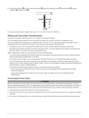
... as radio antenna lines or power cables. Connecting the power cable without the appropriate fuse in place voids the product warranty. 1 Route the power cable from your local Garmin dealer, or you can go to buy.garmin.com (optional). • If needed, you can trim the grommet to enable you to other equipment, you should install the power cable as close to the battery...
... as radio antenna lines or power cables. Connecting the power cable without the appropriate fuse in place voids the product warranty. 1 Route the power cable from your local Garmin dealer, or you can go to buy.garmin.com (optional). • If needed, you can trim the grommet to enable you to other equipment, you should install the power cable as close to the battery...

Installation Instructions
Page 9
... chartplotter is recommended. To download the latest manual, go to extend the cable, the appropriate gauge of wire must be viewing the radar screen for operating instructions. If you have more than one another using a Garmin network cable with larger connectors. ◦ To connect this radar to the battery is connected to support.garmin .com/manuals. This radar provides data to configure...
... chartplotter is recommended. To download the latest manual, go to extend the cable, the appropriate gauge of wire must be viewing the radar screen for operating instructions. If you have more than one another using a Garmin network cable with larger connectors. ◦ To connect this radar to the battery is connected to support.garmin .com/manuals. This radar provides data to configure...

Installation Instructions
Page 10
... or on . Contact Garmin product support for help troubleshoot installation problems. Status LED Color and Activity Radar Status Solid red The radar is not • The wire gauge used , it if necessary. Update the software on the device or on . Contacting Garmin Support • Go to support.garmin.com for assis tance. of these instructions to extend the power cable may have blown. on...
... or on . Contact Garmin product support for help troubleshoot installation problems. Status LED Color and Activity Radar Status Solid red The radar is not • The wire gauge used , it if necessary. Update the software on the device or on . Contacting Garmin Support • Go to support.garmin.com for assis tance. of these instructions to extend the power cable may have blown. on...

Installation Instructions
Page 11
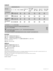
For more information, go to 30 min. Specifications Specification Weight Temperature range Case material Water rating Power output Maximum antenna rotation speed Beam width Maximum range Minimum range Input voltage Fuse Power consumption (typical) Compass-safe distance Measurement GMR 18 HD3 and GMR 18 xHD3: 7 kg (15.4 lb.) GMR 24 xHD3: 8.7 kg (19.2 lb.) From -25 to 70°C (from -13 to 158°...
For more information, go to 30 min. Specifications Specification Weight Temperature range Case material Water rating Power output Maximum antenna rotation speed Beam width Maximum range Minimum range Input voltage Fuse Power consumption (typical) Compass-safe distance Measurement GMR 18 HD3 and GMR 18 xHD3: 7 kg (15.4 lb.) GMR 24 xHD3: 8.7 kg (19.2 lb.) From -25 to 70°C (from -13 to 158°...
Installation Instructions
Page 12
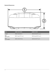
Detailed Dimensions Item Length (width) (height) GMR 18/24 xHD3 508.2 mm (20 in.) 504.7 mm (19 7/8 in.) 248.3 mm (9 ¾ in.) GMR 24 xHD3 645.4 mm (25 7/16 in.) 642.5 mm (25 5/16 in.) 250.3 mm (9 7/8 in.) 12
Detailed Dimensions Item Length (width) (height) GMR 18/24 xHD3 508.2 mm (20 in.) 504.7 mm (19 7/8 in.) 248.3 mm (9 ¾ in.) GMR 24 xHD3 645.4 mm (25 7/16 in.) 642.5 mm (25 5/16 in.) 250.3 mm (9 7/8 in.) 12

Installation Instructions
Page 13
Item GMR 18/24 xHD3 233 mm (9 3/16 in.) 176.7 mm (6 15/16 in.) GMR 24 xHD3 233 mm (9 3/16 in.) 245.4 mm (9 11/16 in.) 141.5 mm (5 9/16 in.) 141.5 mm (5 9/16 in.) 190 mm (7 ½ in.) 139.2 mm (5 ½ in.) 258.5 mm (10 3/16 in.) 207.7 mm (8 3/16 in.) 141.5 mm (5 9/16 in.) 227.5 mm (8 15/16 in.) 141.5 mm (5 9/16 in.) 296.2 mm (9 11/16 in.) Open-Source Software License To view the open-source software license(s) used in this product, go to developer.garmin.com/open-source /linux/. 13
Item GMR 18/24 xHD3 233 mm (9 3/16 in.) 176.7 mm (6 15/16 in.) GMR 24 xHD3 233 mm (9 3/16 in.) 245.4 mm (9 11/16 in.) 141.5 mm (5 9/16 in.) 141.5 mm (5 9/16 in.) 190 mm (7 ½ in.) 139.2 mm (5 ½ in.) 258.5 mm (10 3/16 in.) 207.7 mm (8 3/16 in.) 141.5 mm (5 9/16 in.) 227.5 mm (8 15/16 in.) 141.5 mm (5 9/16 in.) 296.2 mm (9 11/16 in.) Open-Source Software License To view the open-source software license(s) used in this product, go to developer.garmin.com/open-source /linux/. 13
Installation Instructions
Page 14
...-9199 © 2023 Garmin Ltd. GMR™ is a trademark of Garmin. NMEA®, NMEA 2000®, and the NMEA 2000 logo are trademarks of the National Marine Electronics Association. or its subsidiaries. or its subsidiaries support.garmin.com or its subsidiaries, registered in the USA and other countries. These trademarks may not be used without the express...
...-9199 © 2023 Garmin Ltd. GMR™ is a trademark of Garmin. NMEA®, NMEA 2000®, and the NMEA 2000 logo are trademarks of the National Marine Electronics Association. or its subsidiaries. or its subsidiaries support.garmin.com or its subsidiaries, registered in the USA and other countries. These trademarks may not be used without the express...


