
Installation Manual
Page 3
...to the Garmin GDL 51R and GDL 52R unless specifically noted otherwise. NOTE The Bluetooth® word mark and logos are registered trademarks owned by Garmin is a trademark of California to cause cancer, birth defects, or reproductive harm. All rights reserved. 190-02087-10 Rev. 1 GDL 51(R)/52(R) Installation Manual Page i...of Sirius XM Radio Inc. Sirius, XM, SiriusXM, and all reproductions in whole or in this installation manual refer to the Garmin GDL 51 and GDL 52 unless specifically noted otherwise. All other countries. The preceding statement is being provided in this...
...to the Garmin GDL 51R and GDL 52R unless specifically noted otherwise. NOTE The Bluetooth® word mark and logos are registered trademarks owned by Garmin is a trademark of California to cause cancer, birth defects, or reproductive harm. All rights reserved. 190-02087-10 Rev. 1 GDL 51(R)/52(R) Installation Manual Page i...of Sirius XM Radio Inc. Sirius, XM, SiriusXM, and all reproductions in whole or in this installation manual refer to the Garmin GDL 51 and GDL 52 unless specifically noted otherwise. All other countries. The preceding statement is being provided in this...
Installation Manual
Page 6
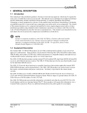
... may compromise your display. 190-02087-10 Rev. 1 GDL 51(R)/52(R) Installation Manual Page 1-1 This manual is not intended for your safety and is not recommended. These products can provide the following data: GPS, SiriusXM weather/audio, ADS-B traffic and weather (52/52R only), attitude and pressure to Garmin® units like the aera 660/795/796, G3X...
... may compromise your display. 190-02087-10 Rev. 1 GDL 51(R)/52(R) Installation Manual Page 1-1 This manual is not intended for your safety and is not recommended. These products can provide the following data: GPS, SiriusXM weather/audio, ADS-B traffic and weather (52/52R only), attitude and pressure to Garmin® units like the aera 660/795/796, G3X...
Installation Manual
Page 7
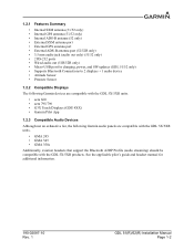
... (51R/52R only) • Micro-USB port for additional information. 190-02087-10 Rev. 1 GDL 51(R)/52(R) Installation Manual Page 1-2 See the applicable pilot's guide and headset manual for charging, power, and SW updates (GDL 51/52 only) • Supports Bluetooth Connections to 2 displays + 1 audio device • Attitude Sensor • Pressure Sensor 1.2.2 Compatible Displays The following Garmin devices are...
... (51R/52R only) • Micro-USB port for additional information. 190-02087-10 Rev. 1 GDL 51(R)/52(R) Installation Manual Page 1-2 See the applicable pilot's guide and headset manual for charging, power, and SW updates (GDL 51/52 only) • Supports Bluetooth Connections to 2 displays + 1 audio device • Attitude Sensor • Pressure Sensor 1.2.2 Compatible Displays The following Garmin devices are...
Installation Manual
Page 8
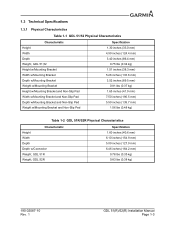
... (139.7 mm) 1.06 lbs (0.48 kg) Table 1-2 GDL 51R/52R Physical Characteristics Characteristic Height Width Depth Depth w/Connector Weight, GDL 51R Weight, GDL 52R Specification 1.60 inches (40.6 mm) 6.10 inches (154.9 mm) 5.00 inches (127.0 mm) 6.46 inches (164.2 mm) 0.78 lbs (0.35 kg) 0.83 lbs (0.38 kg) 190-02087-10 Rev. 1 GDL 51(R)/52(R) Installation Manual Page 1-3
... (139.7 mm) 1.06 lbs (0.48 kg) Table 1-2 GDL 51R/52R Physical Characteristics Characteristic Height Width Depth Depth w/Connector Weight, GDL 51R Weight, GDL 52R Specification 1.60 inches (40.6 mm) 6.10 inches (154.9 mm) 5.00 inches (127.0 mm) 6.46 inches (164.2 mm) 0.78 lbs (0.35 kg) 0.83 lbs (0.38 kg) 190-02087-10 Rev. 1 GDL 51(R)/52(R) Installation Manual Page 1-3
Installation Manual
Page 10
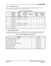
... @ 28V NA 0.84A @ 14V 0.41A @ 28V NA USB Power - Power Specifications Unit GDL 51 GDL 51R GDL 52 GDL 52R Aircraft Power - Table 1-5 GDL 5X/5XR Reference Documents Document G3X/G3X Touch Installation Manual aera 795/796 Pilot's Guide Garmin Pilot User's Guide User's Guide, Garmin Pilot for installing the GDL 5X/5XR. Input voltage range is 10-33 VDC. Unit On, Not...
... @ 28V NA 0.84A @ 14V 0.41A @ 28V NA USB Power - Power Specifications Unit GDL 51 GDL 51R GDL 52 GDL 52R Aircraft Power - Table 1-5 GDL 5X/5XR Reference Documents Document G3X/G3X Touch Installation Manual aera 795/796 Pilot's Guide Garmin Pilot User's Guide User's Guide, Garmin Pilot for installing the GDL 5X/5XR. Input voltage range is 10-33 VDC. Unit On, Not...
Installation Manual
Page 11
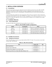
... the following accessories are required to A Style USB, Mass Storage, 0.5m Garmin P/N Qty 145-02489-00 1 253-00503-00 1 320-00239-53 1 320-00559-00 1 190-02087-10 Rev. 1 GDL 51(R)/52(R) Installation Manual Page 2-1 Table 2-1 GDL 5X/5XR Available Configurations Model GDL 51 GDL 51R GDL 52 GDL 52R Part Number 010-01561-40 010-01561-50 010-01561-20 010...
... the following accessories are required to A Style USB, Mass Storage, 0.5m Garmin P/N Qty 145-02489-00 1 253-00503-00 1 320-00239-53 1 320-00559-00 1 190-02087-10 Rev. 1 GDL 51(R)/52(R) Installation Manual Page 2-1 Table 2-1 GDL 5X/5XR Available Configurations Model GDL 51 GDL 51R GDL 52 GDL 52R Part Number 010-01561-40 010-01561-50 010-01561-20 010...
Installation Manual
Page 12
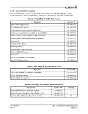
... (010-12498-60) and mounting hardware (not provided) are provided separately from the GDL 51R/52R units. Table 2-3 GDL 51/52 Available Accessories Equipment MCX to BNC Adapter Cable AC Adapter Cable, Micro B Cable Assembly, Data/Power (GDL Bare Wire) Cable Assembly, Data/Power with Mount (aera 660) Mounting Kit Portable ... w/Hardware, Jackscrew 15/26 pin D-Sub Connector Receptacle, Crimp Socket 15 ckt Contact, Socket, Mil Crimp, Size 20, 20-24 AWG Garmin P/N 011-01855-01 330-00625-15 336-00022-02 Quantity 1 1 16 190-02087-10 Rev. 1 GDL 51(R)/52(R) Installation Manual Page 2-2
... (010-12498-60) and mounting hardware (not provided) are provided separately from the GDL 51R/52R units. Table 2-3 GDL 51/52 Available Accessories Equipment MCX to BNC Adapter Cable AC Adapter Cable, Micro B Cable Assembly, Data/Power (GDL Bare Wire) Cable Assembly, Data/Power with Mount (aera 660) Mounting Kit Portable ... w/Hardware, Jackscrew 15/26 pin D-Sub Connector Receptacle, Crimp Socket 15 ckt Contact, Socket, Mil Crimp, Size 20, 20-24 AWG Garmin P/N 011-01855-01 330-00625-15 336-00022-02 Quantity 1 1 16 190-02087-10 Rev. 1 GDL 51(R)/52(R) Installation Manual Page 2-2
Installation Manual
Page 17
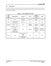
... has several status LEDs visible on the face of the status LEDs. LED Color/ State OFF RED ORANGE GREEN BLUE Table 2-6 GDL 5X/5XR Status LEDs Battery/Power Connext Unit off Charging (solid) Fault (flashing) No active connection Not used Battery = 20...fix Fault Firmware update GPS fix ADS-B (GDL 52/52R only) No Ground Signal SXM No signal Fault Fault Firmware update Firmware update Ground station signal received in the last minute Minimum required or better signal N/A N/A N/A 190-02087-10 Rev. 1 GDL 51(R)/52(R) Installation Manual Page 2-7 Table 2-6 describes the operation of...
... has several status LEDs visible on the face of the status LEDs. LED Color/ State OFF RED ORANGE GREEN BLUE Table 2-6 GDL 5X/5XR Status LEDs Battery/Power Connext Unit off Charging (solid) Fault (flashing) No active connection Not used Battery = 20...fix Fault Firmware update GPS fix ADS-B (GDL 52/52R only) No Ground Signal SXM No signal Fault Fault Firmware update Firmware update Ground station signal received in the last minute Minimum required or better signal N/A N/A N/A 190-02087-10 Rev. 1 GDL 51(R)/52(R) Installation Manual Page 2-7 Table 2-6 describes the operation of...
Installation Manual
Page 20
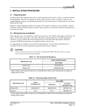
...-10 Rev. 1 GDL 51(R)/52(R) Installation Manual Page 3-1 The installer shall supply and fabricate all input and output signals. All electrical connections to the GDL 51R/52R are subject to prevent movement. 3.2 Wiring Harness Installation Allow adequate space for installation of cables and connectors. Table 3-1. Pin Contact Part Numbers Manufacturer [1] 15-pin D-Subminiature 20-24 AWG Garmin P/N 336-00022-02...
...-10 Rev. 1 GDL 51(R)/52(R) Installation Manual Page 3-1 The installer shall supply and fabricate all input and output signals. All electrical connections to the GDL 51R/52R are subject to prevent movement. 3.2 Wiring Harness Installation Allow adequate space for installation of cables and connectors. Table 3-1. Pin Contact Part Numbers Manufacturer [1] 15-pin D-Subminiature 20-24 AWG Garmin P/N 336-00022-02...
Installation Manual
Page 22
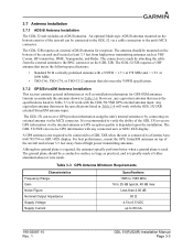
...be mounted on the GDL 52R. Although no ground plane is required, the antenna typically performs better when a ground plane is typically made by connecting an external antenna via the internal antenna as VHF Comm, HF transmitter, DME, Transponder, and Radar. Garmin recommends the antennas ... GPS reception quality is connected to 60 mA 190-02087-10 Rev. 1 GDL 51(R)/52(R) Installation Manual Page 3-3 The ground plane should be connected to a GDL 5XR when the unit is dependent upon the installation. It is recommended to verify the ability of the aircraft and located at ...
...be mounted on the GDL 52R. Although no ground plane is required, the antenna typically performs better when a ground plane is typically made by connecting an external antenna via the internal antenna as VHF Comm, HF transmitter, DME, Transponder, and Radar. Garmin recommends the antennas ... GPS reception quality is connected to 60 mA 190-02087-10 Rev. 1 GDL 51(R)/52(R) Installation Manual Page 3-3 The ground plane should be connected to a GDL 5XR when the unit is dependent upon the installation. It is recommended to verify the ability of the aircraft and located at ...
Installation Manual
Page 28
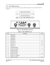
Figure 4-3 View of GDL 51R/52R Connector Figure 4-4 GDL 51R/52R connections Table 4-3 GDL 51R/52R Pin List Pin Pin Name I/O 1 RESERVED -- 2 RESERVED -- 3 RESERVED -- 4 RESERVED -- 5 RS-232 TX 2 Out 6 RS-232 RX 2 In 7 RS-232 TX 1 Out 8 RS-232 RX 1 In 9 ... In 11 SIGNAL GROUND -- 12 SIGNAL GROUND -- 13 MUSIC OUT LEFT Out 14 MUSIC OUT COMMON -- 15 MUSIC OUT RIGHT Out 190-02087-10 Rev. 1 GDL 51(R)/52(R) Installation Manual Page 4-3 4.1.2 GDL 51R/52R Connector Figure 4-3 shows the 15 pin D-sub connector pin numbers and Figure 4-4 shows all...
Figure 4-3 View of GDL 51R/52R Connector Figure 4-4 GDL 51R/52R connections Table 4-3 GDL 51R/52R Pin List Pin Pin Name I/O 1 RESERVED -- 2 RESERVED -- 3 RESERVED -- 4 RESERVED -- 5 RS-232 TX 2 Out 6 RS-232 RX 2 In 7 RS-232 TX 1 Out 8 RS-232 RX 1 In 9 ... In 11 SIGNAL GROUND -- 12 SIGNAL GROUND -- 13 MUSIC OUT LEFT Out 14 MUSIC OUT COMMON -- 15 MUSIC OUT RIGHT Out 190-02087-10 Rev. 1 GDL 51(R)/52(R) Installation Manual Page 4-3 4.1.2 GDL 51R/52R Connector Figure 4-3 shows the 15 pin D-sub connector pin numbers and Figure 4-4 shows all...
Installation Manual
Page 29
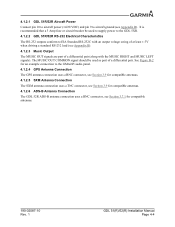
...(see Appendix B). It is recommended that a 3 Amp fuse or circuit breaker be used to supply power to the GDL 5XR. 4.1.2.2 GDL 51R/52R RS-232 Electrical Characteristics The RS-232 outputs conform to the GMA245 audio panel. 4.1.2.4 GPS Antenna Connection The GPS antenna.... 4.1.2.6 ADS-B Antenna Connection The GDL 52R ADS-B antenna connection uses a BNC connector, see Section 3.7.1 for an example connection to EIA Standard RS-232C with the MUSIC RIGHT and MUSIC LEFT signals). See Figure B-2 for compatible antennas. 190-02087-10 Rev. 1 GDL 51(R)/52(R) Installation Manual Page 4-4
...(see Appendix B). It is recommended that a 3 Amp fuse or circuit breaker be used to supply power to the GDL 5XR. 4.1.2.2 GDL 51R/52R RS-232 Electrical Characteristics The RS-232 outputs conform to the GMA245 audio panel. 4.1.2.4 GPS Antenna Connection The GPS antenna.... 4.1.2.6 ADS-B Antenna Connection The GDL 52R ADS-B antenna connection uses a BNC connector, see Section 3.7.1 for an example connection to EIA Standard RS-232C with the MUSIC RIGHT and MUSIC LEFT signals). See Figure B-2 for compatible antennas. 190-02087-10 Rev. 1 GDL 51(R)/52(R) Installation Manual Page 4-4
Installation Manual
Page 33
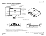
... IMPLIED UNLESS SPECIFICALLY STATED. 3. NOTE 3 3X 2.215 56.26 .285 7.24 GDL 51R=3.20[81.3] GDL 52R=3.08 78.2 C.O.G. NOTE 3 6.16 156.4 5.00 127.0 6.46 164.2 .12 3.0 NOTES: 1. Figure A-2.1 GDL 51R/52R Outline and Installation Drawing 190-02087-10 Rev. 1 GDL 51(R)/52(R) Installation Manual Page A-4 APPENDIX A OUTLINE AND INSTALLATION DRAWINGS .828 21.04 2X 4.500 114.30 2X 2.250 57...
... IMPLIED UNLESS SPECIFICALLY STATED. 3. NOTE 3 3X 2.215 56.26 .285 7.24 GDL 51R=3.20[81.3] GDL 52R=3.08 78.2 C.O.G. NOTE 3 6.16 156.4 5.00 127.0 6.46 164.2 .12 3.0 NOTES: 1. Figure A-2.1 GDL 51R/52R Outline and Installation Drawing 190-02087-10 Rev. 1 GDL 51(R)/52(R) Installation Manual Page A-4 APPENDIX A OUTLINE AND INSTALLATION DRAWINGS .828 21.04 2X 4.500 114.30 2X 2.250 57...
Installation Manual
Page 34
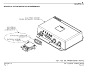
APPENDIX A OUTLINE AND INSTALLATION DRAWINGS GDL 51R 011-03910-50 GDL 52R (SHOWN) 011-03910-30 INCLUDED IN 010-12498-60 CONNECTOR KIT 15 PIN D-SUB CONNECTOR 330-00625-15 BACKSHELL ASSEMBLY 011-01855-01 190-02087-10 Rev. 1 Figure A-2.2 GDL 51R/52R Installation Drawing GDL 51(R)/52(R) Installation Manual Page A-5
APPENDIX A OUTLINE AND INSTALLATION DRAWINGS GDL 51R 011-03910-50 GDL 52R (SHOWN) 011-03910-30 INCLUDED IN 010-12498-60 CONNECTOR KIT 15 PIN D-SUB CONNECTOR 330-00625-15 BACKSHELL ASSEMBLY 011-01855-01 190-02087-10 Rev. 1 Figure A-2.2 GDL 51R/52R Installation Drawing GDL 51(R)/52(R) Installation Manual Page A-5

