

Installation Manual
Page 2
... Aviation Panel-Mount Technical Support Line (Toll Free) 1.888.606.5482 Garmin (Europe) Ltd. Liberty House, Hounsdown Business Park Southampton, Hampshire SO40 9LR U.K. Revision 1 Revision Date 08/04/17 RECORD OF REVISIONS Initial Release Description 190-02087-10 Rev. 1 GDL 51(R)/52(R) Installation Manual Page A Garmin aviation support and warranty information can be reproduced, copied, transmitted, disseminated, downloaded or stored in any storage medium, for...
... Aviation Panel-Mount Technical Support Line (Toll Free) 1.888.606.5482 Garmin (Europe) Ltd. Liberty House, Hounsdown Business Park Southampton, Hampshire SO40 9LR U.K. Revision 1 Revision Date 08/04/17 RECORD OF REVISIONS Initial Release Description 190-02087-10 Rev. 1 GDL 51(R)/52(R) Installation Manual Page A Garmin aviation support and warranty information can be reproduced, copied, transmitted, disseminated, downloaded or stored in any storage medium, for...
Installation Manual
Page 3
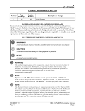
... logos are the property of their respective owners. If you have any and all related marks and logos are trademarks of Apple Inc., registered in this installation manual refer to the Garmin GDL 51R and GDL 52R unless specifically noted otherwise. CURRENT REVISION DESCRIPTION Revision Page Number(s) 1 All Section Number All Initial Release Description of Change INFORMATION SUBJECT TO EXPORT CONTROL LAWS This document...
... logos are the property of their respective owners. If you have any and all related marks and logos are trademarks of Apple Inc., registered in this installation manual refer to the Garmin GDL 51R and GDL 52R unless specifically noted otherwise. CURRENT REVISION DESCRIPTION Revision Page Number(s) 1 All Section Number All Initial Release Description of Change INFORMATION SUBJECT TO EXPORT CONTROL LAWS This document...
Installation Manual
Page 4
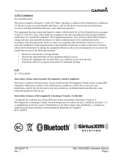
...(s). M/N: A02895 190-02087-10 Rev. 1 GDL 51(R)/52(R) Installation Manual Page ii This equipment has been tested and found to correct the interference by turning the equipment off and on, the user is subject to part 15 of the FCC Rules. Innovation, Sciences et Développment économique Canada - This equipment generates, uses, and can be determined by...
...(s). M/N: A02895 190-02087-10 Rev. 1 GDL 51(R)/52(R) Installation Manual Page ii This equipment has been tested and found to correct the interference by turning the equipment off and on, the user is subject to part 15 of the FCC Rules. Innovation, Sciences et Développment économique Canada - This equipment generates, uses, and can be determined by...
Installation Manual
Page 6
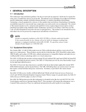
... extent allowable by reference to this information to install equipment by law, Garmin will request this manual assumes use by individuals who do not possess the competencies and abilities set forth above. For questions, please contact Garmin Product Support at 1-888-606-5482. 1.2 Equipment Description The Garmin GDL 51/51R/52/52R products are remote mount versions that includes applicable internal GPS/ SXM/ADS...
... extent allowable by reference to this information to install equipment by law, Garmin will request this manual assumes use by individuals who do not possess the competencies and abilities set forth above. For questions, please contact Garmin Product Support at 1-888-606-5482. 1.2 Equipment Description The Garmin GDL 51/51R/52/52R products are remote mount versions that includes applicable internal GPS/ SXM/ADS...
Installation Manual
Page 7
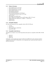
See the applicable pilot's guide and headset manual for charging, power, and SW updates (GDL 51/52 only) • Supports Bluetooth Connections to 2 displays + 1 audio device • Attitude Sensor • Pressure Sensor 1.2.2 Compatible Displays The following Garmin devices are compatible with the GDL 5X/5XR units. • aera 660 • aera 795/796 • G3X Touch Displays (GDU 4XX) • Garmin Pilot App 1.2.3 Compatible Audio Devices Although not an exhaustive...
See the applicable pilot's guide and headset manual for charging, power, and SW updates (GDL 51/52 only) • Supports Bluetooth Connections to 2 displays + 1 audio device • Attitude Sensor • Pressure Sensor 1.2.2 Compatible Displays The following Garmin devices are compatible with the GDL 5X/5XR units. • aera 660 • aera 795/796 • G3X Touch Displays (GDU 4XX) • Garmin Pilot App 1.2.3 Compatible Audio Devices Although not an exhaustive...

Installation Manual
Page 9
1.3.2 General Specifications Table 1-3. General Specifications Characteristic Operating Voltage Temperature Range Maximum Altitude Headphone Output Bluetooth Connectivity USB Port (GDL 5X only) Specification 14/28 VDC refer to Table 1-4 for detailed power requirements -20°C to +60°C (operation) -20°C to +30°C (storage) -20°C to +50°C (short term storage) 0°C to +40°C (battery charging range) 55,000 ft Output amplifiers: 1 Stereo 3.5mm output for lineout/consumer...
1.3.2 General Specifications Table 1-3. General Specifications Characteristic Operating Voltage Temperature Range Maximum Altitude Headphone Output Bluetooth Connectivity USB Port (GDL 5X only) Specification 14/28 VDC refer to Table 1-4 for detailed power requirements -20°C to +60°C (operation) -20°C to +30°C (storage) -20°C to +50°C (short term storage) 0°C to +40°C (battery charging range) 55,000 ft Output amplifiers: 1 Stereo 3.5mm output for lineout/consumer...
Installation Manual
Page 10
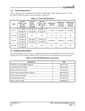
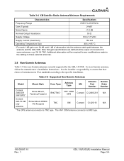
.... 1 GDL 51(R)/52(R) Installation Manual Page 1-5 Table 1-5 GDL 5X/5XR Reference Documents Document G3X/G3X Touch Installation Manual aera 795/796 Pilot's Guide Garmin Pilot User's Guide User's Guide, Garmin Pilot for installing the GDL 5X/5XR. Power Specifications Unit GDL 51 GDL 51R GDL 52 GDL 52R Aircraft Power - Input voltage range is 10-33 VDC. Unit On 0.4 A @ 5V NA 0.67A @ 5V NA USB Power - ing 0.82A @ 14V 0.40A @ 28V NA 0.84A @ 14V 0.41A @ 28V NA USB Power - Unit Off. 1.3.3 Power Requirements...
.... 1 GDL 51(R)/52(R) Installation Manual Page 1-5 Table 1-5 GDL 5X/5XR Reference Documents Document G3X/G3X Touch Installation Manual aera 795/796 Pilot's Guide Garmin Pilot User's Guide User's Guide, Garmin Pilot for installing the GDL 5X/5XR. Power Specifications Unit GDL 51 GDL 51R GDL 52 GDL 52R Aircraft Power - Input voltage range is 10-33 VDC. Unit On 0.4 A @ 5V NA 0.67A @ 5V NA USB Power - ing 0.82A @ 14V 0.40A @ 28V NA 0.84A @ 14V 0.41A @ 28V NA USB Power - Unit Off. 1.3.3 Power Requirements...
Installation Manual
Page 11
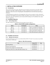
... w/Cable Slot Vehicle Power Adapter 5V 2.0A, Micro-USB Cable Assy, Micro B to installation. The appendices contain interconnect wiring diagrams, mounting dimensions, and information pertaining to A Style USB, Mass Storage, 0.5m Garmin P/N Qty 145-02489-00 1 253-00503-00 1 320-00239-53 1 320-00559-00 1 190-02087-10 Rev. 1 GDL 51(R)/52(R) Installation Manual Page 2-1 Table 2-1 GDL 5X/5XR Available Configurations Model GDL 51 GDL 51R GDL 52 GDL 52R Part Number 010...
... w/Cable Slot Vehicle Power Adapter 5V 2.0A, Micro-USB Cable Assy, Micro B to installation. The appendices contain interconnect wiring diagrams, mounting dimensions, and information pertaining to A Style USB, Mass Storage, 0.5m Garmin P/N Qty 145-02489-00 1 253-00503-00 1 320-00239-53 1 320-00559-00 1 190-02087-10 Rev. 1 GDL 51(R)/52(R) Installation Manual Page 2-1 Table 2-1 GDL 5X/5XR Available Configurations Model GDL 51 GDL 51R GDL 52 GDL 52R Part Number 010...
Installation Manual
Page 12
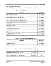
...-02087-10 Rev. 1 GDL 51(R)/52(R) Installation Manual Page 2-2 A single connector kit (010-12498-60) and mounting hardware (not provided) are required to 18 Pin Connector Cable Assembly, Data/Power with Mount (aera 660) Mounting Kit Portable Friction Mount Mounting Bracket Vehicle Power Cable, Micro-USB GA 24 MCX SXM Antenna Carry Case GA 25 MCX External GPS Antenna GA 27C GPS Antenna Kit Garmin P/N 010-10121-00...
...-02087-10 Rev. 1 GDL 51(R)/52(R) Installation Manual Page 2-2 A single connector kit (010-12498-60) and mounting hardware (not provided) are required to 18 Pin Connector Cable Assembly, Data/Power with Mount (aera 660) Mounting Kit Portable Friction Mount Mounting Bracket Vehicle Power Cable, Micro-USB GA 24 MCX SXM Antenna Carry Case GA 25 MCX External GPS Antenna GA 27C GPS Antenna Kit Garmin P/N 010-10121-00...
Installation Manual
Page 13
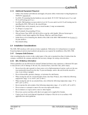
...;C). • Do not remove or attempt to remove the non-user-replaceable battery. • Do not immerse or expose unit to water or other liquids. • Do not use a power and data cable that can be manually reset) circuit breaker (3 Amp recommended). • Tie Wraps or Lacing Cord • Ring Terminals (for part numbers. • Heat shrink tubing 2.4 Installation Considerations The GDL 5XR interfaces with applicable...
...;C). • Do not remove or attempt to remove the non-user-replaceable battery. • Do not immerse or expose unit to water or other liquids. • Do not use a power and data cable that can be manually reset) circuit breaker (3 Amp recommended). • Tie Wraps or Lacing Cord • Ring Terminals (for part numbers. • Heat shrink tubing 2.4 Installation Considerations The GDL 5XR interfaces with applicable...

Installation Manual
Page 15
... direct as possible • Avoid sharp bends • Avoid routing near power sources (e.g. 400 Hz generators, trim motors, etc) or near heat sources. Allow adequate space for wire gauge guidance. If using larger barrel contacts, ensure that uses Bluetooth wireless technology, mount the devices apart from all of the cables. 190-02087-10 Rev. 1 GDL 51(R)/52(R) Installation Manual Page 2-5 NOTE Avoid installing the unit...
... direct as possible • Avoid sharp bends • Avoid routing near power sources (e.g. 400 Hz generators, trim motors, etc) or near heat sources. Allow adequate space for wire gauge guidance. If using larger barrel contacts, ensure that uses Bluetooth wireless technology, mount the devices apart from all of the cables. 190-02087-10 Rev. 1 GDL 51(R)/52(R) Installation Manual Page 2-5 NOTE Avoid installing the unit...

Installation Manual
Page 16
... power dissipation combined with restricted ventilation, or due to heat generated by means of the installation should always be found in the connected display pilot's guide. More information about these configuration items can simultaneously support up , by adjacent equipment. The configuration/adjustments are not intended to the current aircraft attitude. • Compatibility Mode ◦ Using this setting may improve Garmin Pilot Connext data connections. • Auto...
... power dissipation combined with restricted ventilation, or due to heat generated by means of the installation should always be found in the connected display pilot's guide. More information about these configuration items can simultaneously support up , by adjacent equipment. The configuration/adjustments are not intended to the current aircraft attitude. • Compatibility Mode ◦ Using this setting may improve Garmin Pilot Connext data connections. • Auto...
Installation Manual
Page 17
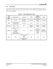
... LEDs Battery/Power Connext Unit off Charging (solid) Fault (flashing) No active connection Not used Battery = 20% OR External power is applied Battery saver feature (flashing) N/A N/A Active connection (solid) OR Pairing list cleared (flashing) GPS No GPS fix Fault Firmware update GPS fix ADS-B (GDL 52/52R only) No Ground Signal SXM No signal Fault Fault Firmware update Firmware update Ground station signal received in the last minute Minimum required or better signal N/A N/A N/A 190-02087-10 Rev. 1 GDL 51(R)/52(R) Installation Manual Page...
... LEDs Battery/Power Connext Unit off Charging (solid) Fault (flashing) No active connection Not used Battery = 20% OR External power is applied Battery saver feature (flashing) N/A N/A Active connection (solid) OR Pairing list cleared (flashing) GPS No GPS fix Fault Firmware update GPS fix ADS-B (GDL 52/52R only) No Ground Signal SXM No signal Fault Fault Firmware update Firmware update Ground station signal received in the last minute Minimum required or better signal N/A N/A N/A 190-02087-10 Rev. 1 GDL 51(R)/52(R) Installation Manual Page...

Installation Manual
Page 18
.... 2.10 Updating Software Software updates for the GDL 5X/5XR can be viewed on the connected display. However, if the software is available in the product box, the unit's S/N tag, and on the System Information Page of the activated services: ◦ For SiriusXM weather, on a connected device, view the Weather Products list and confirm that current software be powered on, facing skyward. 190-02087-10 Rev. 1 GDL 51(R)/52(R) Installation Manual Page 2-8
.... 2.10 Updating Software Software updates for the GDL 5X/5XR can be viewed on the connected display. However, if the software is available in the product box, the unit's S/N tag, and on the System Information Page of the activated services: ◦ For SiriusXM weather, on a connected device, view the Weather Products list and confirm that current software be powered on, facing skyward. 190-02087-10 Rev. 1 GDL 51(R)/52(R) Installation Manual Page 2-8
Installation Manual
Page 19
... shields just at an audio panel signal input. Single-point, in this manual should be isolated from other equipment. Interference can sneak into audio system interconnecting cables by ground differentials, a common cause of equipment share a single common ground connection back to severe vibration. • The mounting location for the unit should be mounted to the aircraft with the LED...
... shields just at an audio panel signal input. Single-point, in this manual should be isolated from other equipment. Interference can sneak into audio system interconnecting cables by ground differentials, a common cause of equipment share a single common ground connection back to severe vibration. • The mounting location for the unit should be mounted to the aircraft with the LED...
Installation Manual
Page 20
...-00022-02 Military P/N M39029/63-368 [1] Non-Garmin part numbers shown are not maintained by Garmin and consequently are subject to change without notice. 190-02087-10 Rev. 1 GDL 51(R)/52(R) Installation Manual Page 3-1 Retain the original shipping containers for errors before installing the GDL 51R/52R. The installer shall supply and fabricate all cables. If the unit is large enough to accommodate sufficient packing...
...-00022-02 Military P/N M39029/63-368 [1] Non-Garmin part numbers shown are not maintained by Garmin and consequently are subject to change without notice. 190-02087-10 Rev. 1 GDL 51(R)/52(R) Installation Manual Page 3-1 Retain the original shipping containers for errors before installing the GDL 51R/52R. The installer shall supply and fabricate all cables. If the unit is large enough to accommodate sufficient packing...

Installation Manual
Page 21
... the installer. The GDL 5XR will be mounted on condition' only. Trim the coaxial cable to the unit location. The GDL 5XR will mount remotely. WARNING When installing the GDL 5X in accordance with aircraft operating controls or obstruct the pilot's view. 3.6 Continued Airworthiness Other than for cable preparation. 3.5 Equipment Mounting The GDL 5X can be secured to the airframe using the Shield Block. Route the coaxial cable...
... the installer. The GDL 5XR will be mounted on condition' only. Trim the coaxial cable to the unit location. The GDL 5XR will mount remotely. WARNING When installing the GDL 5X in accordance with aircraft operating controls or obstruct the pilot's view. 3.6 Continued Airworthiness Other than for cable preparation. 3.5 Equipment Mounting The GDL 5X can be secured to the airframe using the Shield Block. Route the coaxial cable...
Installation Manual
Page 22
... power transmitting antennas such as installation information for reception. However, any connected aera or GDU 4XX display. The GDL 5X can receive GPS position information using the unit's internal antenna or by attaching the cable from the external antenna to verify the ability of the aircraft and located at 1090 MHz. • TSO-C66, TSO-C74, or TSO-C112 antennas that meets the following specifications...
... power transmitting antennas such as installation information for reception. However, any connected aera or GDU 4XX display. The GDL 5X can receive GPS position information using the unit's internal antenna or by attaching the cable from the external antenna to verify the ability of the aircraft and located at 1090 MHz. • TSO-C66, TSO-C74, or TSO-C112 antennas that meets the following specifications...
Installation Manual
Page 23
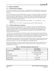
Table 3-4 XM Satellite Radio Antenna Minimum Requirements Characteristics Specifications Frequency Range 2332.5 to 2345 MHz Gain (Typical) 24 dB* Noise Figure
Table 3-4 XM Satellite Radio Antenna Minimum Requirements Characteristics Specifications Frequency Range 2332.5 to 2345 MHz Gain (Typical) 24 dB* Noise Figure
Installation Manual
Page 25
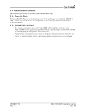
....2 Connext Data Link Check 1. Applying power to pair the display with the GDL 5X/5XR or for configuring the serial port for wired connections. 2. See the applicable display Pilot's Guide to either the GDL 5X or GDL 5XR will be performed in Section 2.9 are receiving the proper information from the GDL 5X/5XR. 3. Verify that any connected devices are set accordingly. 190-02087-10 Rev. 1 GDL 51(R)/52(R) Installation Manual Page...
....2 Connext Data Link Check 1. Applying power to pair the display with the GDL 5X/5XR or for configuring the serial port for wired connections. 2. See the applicable display Pilot's Guide to either the GDL 5X or GDL 5XR will be performed in Section 2.9 are receiving the proper information from the GDL 5X/5XR. 3. Verify that any connected devices are set accordingly. 190-02087-10 Rev. 1 GDL 51(R)/52(R) Installation Manual Page...


