

Installation Manual
Page 2
.... Liberty House, Hounsdown Business Park Southampton, Hampshire SO40 9LR U.K. Garmin aviation support and warranty information can be viewed and to be found at...of this manual or any unauthorized commercial distribution of Garmin. Garmin International, Inc. 1200 E. 151st Street Olathe, KS 66062 USA Aviation Panel-Mount Technical Support Line (Toll Free) 1.888.606.5482 Garmin (Europe) Ltd. Garmin hereby grants permission to download a single copy of... Date 08/04/17 RECORD OF REVISIONS Initial Release Description 190-02087-10 Rev. 1 GDL 51(R)/52(R) Installation Manual Page A
.... Liberty House, Hounsdown Business Park Southampton, Hampshire SO40 9LR U.K. Garmin aviation support and warranty information can be viewed and to be found at...of this manual or any unauthorized commercial distribution of Garmin. Garmin International, Inc. 1200 E. 151st Street Olathe, KS 66062 USA Aviation Panel-Mount Technical Support Line (Toll Free) 1.888.606.5482 Garmin (Europe) Ltd. Garmin hereby grants permission to download a single copy of... Date 08/04/17 RECORD OF REVISIONS Initial Release Description 190-02087-10 Rev. 1 GDL 51(R)/52(R) Installation Manual Page A

Installation Manual
Page 5
... Requirements 2-9 Section 3 Installation Procedure 3-1 3.1 Unpacking Unit...3-1 3.2 Wiring Harness Installation 3-1 3.3 Backshell Assembly...3-2 3.4 Coax Cable Installation...3-2 3.5 Equipment Mounting ...3-2 3.6 Continued Airworthiness 3-2 3.7 Antenna Installation ...3-3 3.8 Non-Garmin Antennas ...3-4 3.9 Garmin Antennas ...3-5 3.10 Post Installation Checkout 3-6 Section 4 System Interconnects 4-1 4.1 Pin Function List...4-1 Appendix A Outline and Installation Drawings A-1 Appendix B Interconnect Drawings B-1 190-02087-10 Rev. 1 GDL 51(R)/52(R) Installation Manual Page iii
... Requirements 2-9 Section 3 Installation Procedure 3-1 3.1 Unpacking Unit...3-1 3.2 Wiring Harness Installation 3-1 3.3 Backshell Assembly...3-2 3.4 Coax Cable Installation...3-2 3.5 Equipment Mounting ...3-2 3.6 Continued Airworthiness 3-2 3.7 Antenna Installation ...3-3 3.8 Non-Garmin Antennas ...3-4 3.9 Garmin Antennas ...3-5 3.10 Post Installation Checkout 3-6 Section 4 System Interconnects 4-1 4.1 Pin Function List...4-1 Appendix A Outline and Installation Drawings A-1 Appendix B Interconnect Drawings B-1 190-02087-10 Rev. 1 GDL 51(R)/52(R) Installation Manual Page iii
Installation Manual
Page 6
... cases, to install these functions in range of a ground station, the GDL 52/ 52R will request this information over wired connections. For questions, please contact Garmin Product Support at 1-888-606-5482. 1.2 Equipment Description The Garmin GDL 51/51R/52/52R products are remote mount versions that includes applicable internal GPS/ SXM/ADS-B antennas, and an internal...
... cases, to install these functions in range of a ground station, the GDL 52/ 52R will request this information over wired connections. For questions, please contact Garmin Product Support at 1-888-606-5482. 1.2 Equipment Description The Garmin GDL 51/51R/52/52R products are remote mount versions that includes applicable internal GPS/ SXM/ADS-B antennas, and an internal...
Installation Manual
Page 8
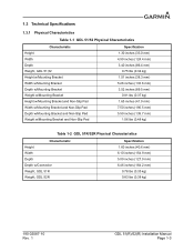
1.3 Technical Specifications 1.3.1 Physical Characteristics Table 1-1 GDL 51/52 Physical Characteristics Characteristic Height Width Depth Weight, GDL 51,52 Height w/Mounting Bracket Width w/Mounting Bracket Depth w/Mounting Bracket Weight w/Mounting Bracket Height w/Mounting Bracket and Non-Slip Pad Width w/Mounting Bracket and Non-Slip Pad Depth w/Mounting Bracket and Non-Slip Pad Weight w/Mounting Bracket and Non-Slip Pad Specification 1.30 inches (33.0 mm...
1.3 Technical Specifications 1.3.1 Physical Characteristics Table 1-1 GDL 51/52 Physical Characteristics Characteristic Height Width Depth Weight, GDL 51,52 Height w/Mounting Bracket Width w/Mounting Bracket Depth w/Mounting Bracket Weight w/Mounting Bracket Height w/Mounting Bracket and Non-Slip Pad Width w/Mounting Bracket and Non-Slip Pad Depth w/Mounting Bracket and Non-Slip Pad Weight w/Mounting Bracket and Non-Slip Pad Specification 1.30 inches (33.0 mm...
Installation Manual
Page 11
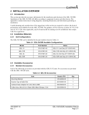
... by the part numbers listed in this section are provided with the GDL 51/52 units. Careful planning and consideration of the GDL 5X/5XR will differ according to installation. Table 2-2 GDL 5X Accessories Item Mounting Bracket Suction Cup w/Cable Slot Vehicle Power Adapter 5V 2.0A, Micro...A Style USB, Mass Storage, 0.5m Garmin P/N Qty 145-02489-00 1 253-00503-00 1 320-00239-53 1 320-00559-00 1 190-02087-10 Rev. 1 GDL 51(R)/52(R) Installation Manual Page 2-1 Table 2-1 GDL 5X/5XR Available Configurations Model GDL 51 GDL 51R GDL 52 GDL 52R Part Number 010-01561-40 010-...
... by the part numbers listed in this section are provided with the GDL 51/52 units. Careful planning and consideration of the GDL 5X/5XR will differ according to installation. Table 2-2 GDL 5X Accessories Item Mounting Bracket Suction Cup w/Cable Slot Vehicle Power Adapter 5V 2.0A, Micro...A Style USB, Mass Storage, 0.5m Garmin P/N Qty 145-02489-00 1 253-00503-00 1 320-00239-53 1 320-00559-00 1 190-02087-10 Rev. 1 GDL 51(R)/52(R) Installation Manual Page 2-1 Table 2-1 GDL 5X/5XR Available Configurations Model GDL 51 GDL 51R GDL 52 GDL 52R Part Number 010-01561-40 010-...
Installation Manual
Page 12
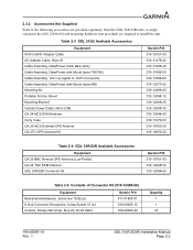
... AWG Garmin P/N 011-01855-01 330-00625-15 336-00022-02 Quantity 1 1 16 190-02087-10 Rev. 1 GDL 51(R)/52(R) Installation Manual Page 2-2 Table 2-3 GDL 51/52 Available Accessories Equipment MCX to BNC Adapter Cable AC Adapter Cable, Micro B Cable Assembly, Data/Power (GDL Bare Wire) Cable Assembly, Data/Power with Mount (aera 660) Mounting Kit Portable Friction Mount Mounting...
... AWG Garmin P/N 011-01855-01 330-00625-15 336-00022-02 Quantity 1 1 16 190-02087-10 Rev. 1 GDL 51(R)/52(R) Installation Manual Page 2-2 Table 2-3 GDL 51/52 Available Accessories Equipment MCX to BNC Adapter Cable AC Adapter Cable, Micro B Cable Assembly, Data/Power (GDL Bare Wire) Cable Assembly, Data/Power with Mount (aera 660) Mounting Kit Portable Friction Mount Mounting...
Installation Manual
Page 13
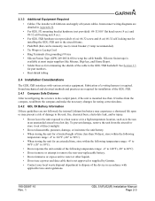
...; Ring Terminals (for installing the GDL 5XR unit to the aircraft frame. • Push/Pull (that is not approved or supplied by Garmin. • Contact your local waste...the necessary changes for noting correction data. 2.4.2 GDL 5X Battery Information If these guidelines are detailed in Appendix B. • For GDL 5X mounting bracket hardware (not provided): #8-32 100°.... • Heat shrink tubing 2.4 Installation Considerations The GDL 5XR interfaces with applicable laws and regulations. 190-02087-10 Rev. 1 GDL 51(R)/52(R) Installation Manual Page 2-3 Fabrication of damage to the ...
...; Ring Terminals (for installing the GDL 5XR unit to the aircraft frame. • Push/Pull (that is not approved or supplied by Garmin. • Contact your local waste...the necessary changes for noting correction data. 2.4.2 GDL 5X Battery Information If these guidelines are detailed in Appendix B. • For GDL 5X mounting bracket hardware (not provided): #8-32 100°.... • Heat shrink tubing 2.4 Installation Considerations The GDL 5XR interfaces with applicable laws and regulations. 190-02087-10 Rev. 1 GDL 51(R)/52(R) Installation Manual Page 2-3 Fabrication of damage to the ...
Installation Manual
Page 14
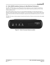
... body type (metal or fiberglass) and the surrounding structures/equipment. For best performance, mount the GDL 5XR with the front of the Connext enabled devices. Figure 2-1 GDL 5X Connext Antenna Location 190-02087-10 Rev. 1 GDL 51(R)/52(R) Installation Manual Page 2-4 2.5 GDL 5X/5XR Installation Guidance for each installation depending on the front face of the...
... body type (metal or fiberglass) and the surrounding structures/equipment. For best performance, mount the GDL 5XR with the front of the Connext enabled devices. Figure 2-1 GDL 5X Connext Antenna Location 190-02087-10 Rev. 1 GDL 51(R)/52(R) Installation Manual Page 2-4 2.5 GDL 5X/5XR Installation Guidance for each installation depending on the front face of the...

Installation Manual
Page 15
... wire gauge guidance. NOTE If poor Connext wireless performance is observed, check the auto reconnect settings and disable any devices that are mounted directly adjacent to each other as much as this is not possible, ensure that additional cooling is located on the front face of... the cables. 190-02087-10 Rev. 1 GDL 51(R)/52(R) Installation Manual Page 2-5 If using larger barrel contacts, ensure that uses Bluetooth wireless technology, mount the devices apart from all of the unit as possible • Avoid sharp bends • Avoid...
... wire gauge guidance. NOTE If poor Connext wireless performance is observed, check the auto reconnect settings and disable any devices that are mounted directly adjacent to each other as much as this is not possible, ensure that additional cooling is located on the front face of... the cables. 190-02087-10 Rev. 1 GDL 51(R)/52(R) Installation Manual Page 2-5 If using larger barrel contacts, ensure that uses Bluetooth wireless technology, mount the devices apart from all of the unit as possible • Avoid sharp bends • Avoid...
Installation Manual
Page 19
... pulse equipment (strobes, spark plugs, magnetos, EL displays, CRTs, etc). Good aircraft electrical/charging system ground bonding is mounted using a GDL 5X mounting bracket (Appendix A-1.2). The wiring diagrams and accompanying notes in which return currents can produce an additive effect at one path in... the various equipment operating in this manual should be protected from nearby high-power equipment. 190-02087-10 Rev. 1 GDL 51(R)/52(R) Installation Manual Page 2-9 This is more than one end eliminates another potential ground loop injection point. Single-point grounding ...
... pulse equipment (strobes, spark plugs, magnetos, EL displays, CRTs, etc). Good aircraft electrical/charging system ground bonding is mounted using a GDL 5X mounting bracket (Appendix A-1.2). The wiring diagrams and accompanying notes in which return currents can produce an additive effect at one path in... the various equipment operating in this manual should be protected from nearby high-power equipment. 190-02087-10 Rev. 1 GDL 51(R)/52(R) Installation Manual Page 2-9 This is more than one end eliminates another potential ground loop injection point. Single-point grounding ...

Installation Manual
Page 21
...coaxial cable to the desired length and install the connector. Trim the coaxial cable to the unit location. 3.3 Backshell Assembly Garmin's backshell gives the installer the ability to easily terminate shield grounds at the backshell housing using six screws supplied by the...approval or endorsement. 190-02087-10 Rev. 1 GDL 51(R)/52(R) Installation Manual Page 3-2 The GDL 5XR will be mounted on condition' only. Instructions for Continued Airworthiness (ICA) are not required for cable preparation. 3.5 Equipment Mounting The GDL 5X can be secured to the outline and installation ...
...coaxial cable to the desired length and install the connector. Trim the coaxial cable to the unit location. 3.3 Backshell Assembly Garmin's backshell gives the installer the ability to easily terminate shield grounds at the backshell housing using six screws supplied by the...approval or endorsement. 190-02087-10 Rev. 1 GDL 51(R)/52(R) Installation Manual Page 3-2 The GDL 5XR will be mounted on condition' only. Instructions for Continued Airworthiness (ICA) are not required for cable preparation. 3.5 Equipment Mounting The GDL 5X can be secured to the outline and installation ...
Installation Manual
Page 22
... < 1.7:1 at 978 MHz and < 1.5:1 at least 3.3 feet away from the external antenna to the GDL 52 via the internal antenna as installation information for reception. For best performance, mount the GPS, SiriusXM antennas on the bottom exterior of the aircraft and at 1090 MHz. • TSO-...section contains general information as well as GPS reception quality is connected to 60 mA 190-02087-10 Rev. 1 GDL 51(R)/52(R) Installation Manual Page 3-3 Garmin recommends the antennas shown in Table 3-4 will work with any equivalent antenna that meets the specifications listed in Table ...
... < 1.7:1 at 978 MHz and < 1.5:1 at least 3.3 feet away from the external antenna to the GDL 52 via the internal antenna as installation information for reception. For best performance, mount the GPS, SiriusXM antennas on the bottom exterior of the aircraft and at 1090 MHz. • TSO-...section contains general information as well as GPS reception quality is connected to 60 mA 190-02087-10 Rev. 1 GDL 51(R)/52(R) Installation Manual Page 3-3 Garmin recommends the antennas shown in Table 3-4 will work with any equivalent antenna that meets the specifications listed in Table ...
Installation Manual
Page 23
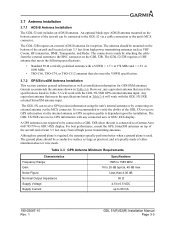
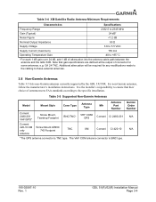
Table 3-4 XM Satellite Radio Antenna Minimum Requirements Characteristics Specifications Frequency Range 2332.5 to 2345 MHz Gain (Typical) 24 dB* Noise Figure
Table 3-4 XM Satellite Radio Antenna Minimum Requirements Characteristics Specifications Frequency Range 2332.5 to 2345 MHz Gain (Typical) 24 dB* Noise Figure

Installation Manual
Page 24
...of antenna meets FAA standards according to the GDL 5X/5XR. 3.9 Garmin Antennas NOTE See the G3X/G3X Touch Installation Manual (190-01115-01) for in -cabin mounting) Flange, Magnetic, or Suction Cup Mounts (for detailed GPS antenna installation information. ...Mounts (for in-cabin mounting) Thru-Mount (tear drop form factor) Thru-Mount (ARINC 743 form factor) Stud Mount (tear drop form factor) Thru-Mount (ARINC 743 form factor) Flange, Magnetic, or Suction Cup Mounts (for in-cabin mounting) Flange, Magnetic, or Suction Cup Mounts (for in -cabin mounting) 190-02087-10 Rev. 1 GDL 51(R)/52...
...of antenna meets FAA standards according to the GDL 5X/5XR. 3.9 Garmin Antennas NOTE See the G3X/G3X Touch Installation Manual (190-01115-01) for in -cabin mounting) Flange, Magnetic, or Suction Cup Mounts (for detailed GPS antenna installation information. ...Mounts (for in-cabin mounting) Thru-Mount (tear drop form factor) Thru-Mount (ARINC 743 form factor) Stud Mount (tear drop form factor) Thru-Mount (ARINC 743 form factor) Flange, Magnetic, or Suction Cup Mounts (for in-cabin mounting) Flange, Magnetic, or Suction Cup Mounts (for in -cabin mounting) 190-02087-10 Rev. 1 GDL 51(R)/52...

Installation Manual
Page 31
MOUNTING HOLES ARE FOR #8 100° FLAT HEAD SCREWS. METRIC VALUES ARE FOR REFERENCE ONLY. 2. DIMENSIONS ARE NOMINAL AND TOLERANCES ARE NOT IMPLIED UNLESS SPECIFICALLY STATED. 3. DIMENSIONS: INCHES[mm]. Figure A-1.2 GDL 51/52 with Mounting Bracket Outline and Installation Drawing GDL 51(R)/52(R) Installation Manual Page A-2 APPENDIX A OUTLINE AND INSTALLATION DRAWINGS WITH MOUNTING BRACKET 3.52 89.5 2X 1.188 30.16 .177 4.50 THRU ALL .344 8.74 X 100° NOTE 3 2X 1.500 38.10 190-02087-10 Rev. 1 1.51 38.3 5.26 133.6 NOTES: 1.
MOUNTING HOLES ARE FOR #8 100° FLAT HEAD SCREWS. METRIC VALUES ARE FOR REFERENCE ONLY. 2. DIMENSIONS ARE NOMINAL AND TOLERANCES ARE NOT IMPLIED UNLESS SPECIFICALLY STATED. 3. DIMENSIONS: INCHES[mm]. Figure A-1.2 GDL 51/52 with Mounting Bracket Outline and Installation Drawing GDL 51(R)/52(R) Installation Manual Page A-2 APPENDIX A OUTLINE AND INSTALLATION DRAWINGS WITH MOUNTING BRACKET 3.52 89.5 2X 1.188 30.16 .177 4.50 THRU ALL .344 8.74 X 100° NOTE 3 2X 1.500 38.10 190-02087-10 Rev. 1 1.51 38.3 5.26 133.6 NOTES: 1.

Installation Manual
Page 32
APPENDIX A OUTLINE AND INSTALLATION DRAWINGS WITH MOUNTING BRACKET & NON-SLIP PAD ACCESSOSRY 5.50 139.7 190-02087-10 Rev. 1 1.65 41.9 7.50 190.5 Figure A-1.3 GDL 51/52 with Mounting Bracket and Pad Outline and Installation Drawing GDL 51(R)/52(R) Installation Manual Page A-3
APPENDIX A OUTLINE AND INSTALLATION DRAWINGS WITH MOUNTING BRACKET & NON-SLIP PAD ACCESSOSRY 5.50 139.7 190-02087-10 Rev. 1 1.65 41.9 7.50 190.5 Figure A-1.3 GDL 51/52 with Mounting Bracket and Pad Outline and Installation Drawing GDL 51(R)/52(R) Installation Manual Page A-3
Installation Manual
Page 33
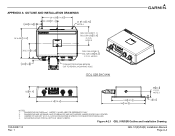
.../52R Outline and Installation Drawing 190-02087-10 Rev. 1 GDL 51(R)/52(R) Installation Manual Page A-4 NOTE 3 3X 2.215 56.26 .285 7.24 GDL 51R=3.20[81.3] GDL 52R=3.08 78.2 C.O.G. METRIC VALUES ARE FOR REFERENCE ONLY. 2. NOTE 3 CONNECTOR SHOWN BROKEN OUT TO REVEAL MOUNTING HOLE GDL 52R SHOWN 1.63 41.4 .88 22.4 C.O.G. CENTER OF GRAVITY (C.O.G.) LOCATION...
.../52R Outline and Installation Drawing 190-02087-10 Rev. 1 GDL 51(R)/52(R) Installation Manual Page A-4 NOTE 3 3X 2.215 56.26 .285 7.24 GDL 51R=3.20[81.3] GDL 52R=3.08 78.2 C.O.G. METRIC VALUES ARE FOR REFERENCE ONLY. 2. NOTE 3 CONNECTOR SHOWN BROKEN OUT TO REVEAL MOUNTING HOLE GDL 52R SHOWN 1.63 41.4 .88 22.4 C.O.G. CENTER OF GRAVITY (C.O.G.) LOCATION...


