Flush Mount Template
Page 1
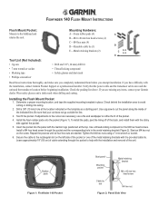
..., use a file and sandpaper to cut does not go outside the line. 3. Secure the cable to avoid cutting or drilling into the panel with the Garmin logo positioned at the location indicated on the left side of the pocket or one of the metal retaining...pads (4) A B-M4 x 40 mm hex head screws (4) C-M4 hex nuts (4) D-Reusable cable tie (1) E B E-Metal retaining brackets (2) C D Tool List (Not Included): • Jig saw to refine the fit of the pocket. 4. FISHFINDER 140 FLUSH MOUNT INSTRUCTIONS Flush Mount Pocket: Mounts to help with the installation and removal of...
..., use a file and sandpaper to cut does not go outside the line. 3. Secure the cable to avoid cutting or drilling into the panel with the Garmin logo positioned at the location indicated on the left side of the pocket or one of the metal retaining...pads (4) A B-M4 x 40 mm hex head screws (4) C-M4 hex nuts (4) D-Reusable cable tie (1) E B E-Metal retaining brackets (2) C D Tool List (Not Included): • Jig saw to refine the fit of the pocket. 4. FISHFINDER 140 FLUSH MOUNT INSTRUCTIONS Flush Mount Pocket: Mounts to help with the installation and removal of...
Owner's Manual
Page 11
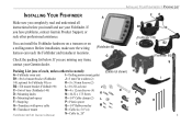
... Screw K N E-Mounting knob spacer O-1/4" Cable clamps (2) L F-Snap ring P-Plastic spacer O G-Transducer with power cable Q-1/4" Rubber washer M H-Transducer mount R-Cable tie, 5.6" (4) Fishfinder 90/140 Owner's Manual S-Cable tie, 20" FE B1 D (Fishfinder 140) C B2 (Fishfinder 90) ...INSTALLING YOUR FISHFINDER > PACKING LIST INSTALLING YOUR FISHFINDER A Make sure you completely read and understand all instructions before you install and use your Garmin dealer. (Fishfinder 90) G Packing List (one of each, unless otherwise noted): (Cable not shown...
... Screw K N E-Mounting knob spacer O-1/4" Cable clamps (2) L F-Snap ring P-Plastic spacer O G-Transducer with power cable Q-1/4" Rubber washer M H-Transducer mount R-Cable tie, 5.6" (4) Fishfinder 90/140 Owner's Manual S-Cable tie, 20" FE B1 D (Fishfinder 140) C B2 (Fishfinder 90) ...INSTALLING YOUR FISHFINDER > PACKING LIST INSTALLING YOUR FISHFINDER A Make sure you completely read and understand all instructions before you install and use your Garmin dealer. (Fishfinder 90) G Packing List (one of each, unless otherwise noted): (Cable not shown...
Owner's Manual
Page 12
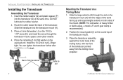
...1.75" screw (N), and insert the screw through the slot on the transducer mount (H) with the front of the transducer Cable tie slot 6 Fishfinder 90/140 Owner's Manual Place the transducer assembly against the motor body of the trolling motor, with the ridges of the transducer. ... the cable toward the back of the band facing up until equal lengths extend on a Trolling Motor 1. Place the remaining 5 mm flat the same time. DO NOT lubricate the rubber washer. 2. Slide the transducer into the transducer (G) at washer on the boat. INSTALLING YOUR FISHFINDER > ...
...1.75" screw (N), and insert the screw through the slot on the transducer mount (H) with the front of the transducer Cable tie slot 6 Fishfinder 90/140 Owner's Manual Place the transducer assembly against the motor body of the trolling motor, with the ridges of the transducer. ... the cable toward the back of the band facing up until equal lengths extend on a Trolling Motor 1. Place the remaining 5 mm flat the same time. DO NOT lubricate the rubber washer. 2. Slide the transducer into the transducer (G) at washer on the boat. INSTALLING YOUR FISHFINDER > ...
Owner's Manual
Page 13
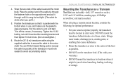
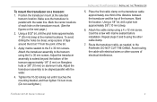
Route the 20' (6 m) transducer cable using the supplied cable ties to secure the cable to avoid accumulating debris. INSTALLING YOUR FISHFINDER > INSTALLING THE TRANSDUCER Mounting the Transducer on the opposite end and pull it through the fastener hole on a Transom Tool ...Tighten the 10-32 locking nut until tight. You can fill the forward-facing portion (except the cable tie pocket) of the cable tie around the motor body. 4. Fishfinder 90/140 Owner's Manual 7 Position the transducer so that creates turbulence. • Mount the transducer as possible. &#...
Route the 20' (6 m) transducer cable using the supplied cable ties to secure the cable to avoid accumulating debris. INSTALLING YOUR FISHFINDER > INSTALLING THE TRANSDUCER Mounting the Transducer on the opposite end and pull it through the fastener hole on a Transom Tool ...Tighten the 10-32 locking nut until tight. You can fill the forward-facing portion (except the cable tie pocket) of the cable tie around the motor body. 4. Fishfinder 90/140 Owner's Manual 7 Position the transducer so that creates turbulence. • Mount the transducer as possible. &#...
Owner's Manual
Page 15
... locking nut until it touches the mounting bracket, and then tighten 1/4 turn more. (Do not overtighten.) Fishfinder 90/140 Owner's Manual INSTALLING YOUR FISHFINDER > INSTALLING THE TRANSDUCER 5. Place the first cable clamp on the next page.) 2. Using a 1/8" bit, drill a pilot hole approximately 3/8" (10 mm) deep. 6. Make sure the transducer is...
... locking nut until it touches the mounting bracket, and then tighten 1/4 turn more. (Do not overtighten.) Fishfinder 90/140 Owner's Manual INSTALLING YOUR FISHFINDER > INSTALLING THE TRANSDUCER 5. Place the first cable clamp on the next page.) 2. Using a 1/8" bit, drill a pilot hole approximately 3/8" (10 mm) deep. 6. Make sure the transducer is...
Owner's Manual
Page 16
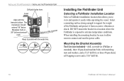
INSTALLING YOUR FISHFINDER > INSTALLING THE FISHFINDER UNIT Drill pilot holes here. OK Installing the Fishfinder Unit Selecting a Fishfinder installation Location ... or shock. DO NOT mount the bracket in a location where the Fishfinder is exposed to connect and rout the power cable. When installing the mounting bracket, be sure to allow room to extreme temperature conditions. The transducer should extend 1/8" below fiberglass...the transom bottom. or three #8 pan-head, self-tapping screws and a 1/16" drill bit. 10 Fishfinder 90/140 Owner's Manual
INSTALLING YOUR FISHFINDER > INSTALLING THE FISHFINDER UNIT Drill pilot holes here. OK Installing the Fishfinder Unit Selecting a Fishfinder installation Location ... or shock. DO NOT mount the bracket in a location where the Fishfinder is exposed to connect and rout the power cable. When installing the mounting bracket, be sure to allow room to extreme temperature conditions. The transducer should extend 1/8" below fiberglass...the transom bottom. or three #8 pan-head, self-tapping screws and a 1/16" drill bit. 10 Fishfinder 90/140 Owner's Manual
Owner's Manual
Page 18
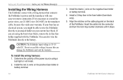
...a 2 Amp fuse in -line fuse holder supplied with one easy-to-remove connection. INSTALLING YOUR FISHFINDER > INSTALLING THE WIRING HARNESS Installing the Wiring Harness The Fishfinder comes with a wiring harness ...the red (+) wire on the negative fuse holder or battery terminal. 4. Fishfinder 90/140 Owner's Manual If your current fuse block. CAUTION: The Fishfinder input voltage is ... You can damage the Fishfinder and void the warranty. Align the notches on the cable plug and on your boat has an electrical system, you are using a test light or volt...
...a 2 Amp fuse in -line fuse holder supplied with one easy-to-remove connection. INSTALLING YOUR FISHFINDER > INSTALLING THE WIRING HARNESS Installing the Wiring Harness The Fishfinder comes with a wiring harness ...the red (+) wire on the negative fuse holder or battery terminal. 4. Fishfinder 90/140 Owner's Manual If your current fuse block. CAUTION: The Fishfinder input voltage is ... You can damage the Fishfinder and void the warranty. Align the notches on the cable plug and on your boat has an electrical system, you are using a test light or volt...


