
Owners Manual PDF
Page 14
Chart Layers You can display laylines on the leeward sailing angle. Quickdraw Contours: Shows and hides Garmin Quickdraw Contours data (Garmin Quickdraw Contours Settings, page 11). Service Points: Shows locations for aerial photos (Viewing Aerial Photos of the changes in the boat's heading ...on the tide. When in the direction of the wind angle or direction provided by your installed charts or your present location on both land and sea portions of the charts. The Manual option calculates the laylines using the measured wind angle from the bow of the boat in sailing...
Chart Layers You can display laylines on the leeward sailing angle. Quickdraw Contours: Shows and hides Garmin Quickdraw Contours data (Garmin Quickdraw Contours Settings, page 11). Service Points: Shows locations for aerial photos (Viewing Aerial Photos of the changes in the boat's heading ...on the tide. When in the direction of the wind angle or direction provided by your installed charts or your present location on both land and sea portions of the charts. The Manual option calculates the laylines using the measured wind angle from the bow of the boat in sailing...

Owners Manual PDF
Page 26
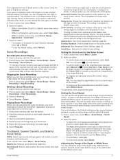
...transducers with all models. TIP: To reset the pin and measure from another ECHOMAP Ultra device and Garmin ClearVü transducer mounted at the selected location. 4 Select another location....best after you must fully rotate your boat. 1 From a sonar view, select Menu > Sonar Setup > Installation > Transducer Type. 2 Select the transducer to change the source. 2 Select Menu > Sonar Setup > ... Gain or Brightness. 3 Select an option: • To increase or decrease the gain or brightness manually, select Up or Down. • To allow the chartplotter to view historical sonar data. Renaming ...
...transducers with all models. TIP: To reset the pin and measure from another ECHOMAP Ultra device and Garmin ClearVü transducer mounted at the selected location. 4 Select another location....best after you must fully rotate your boat. 1 From a sonar view, select Menu > Sonar Setup > Installation > Transducer Type. 2 Select the transducer to change the source. 2 Select Menu > Sonar Setup > ... Gain or Brightness. 3 Select an option: • To increase or decrease the gain or brightness manually, select Up or Down. • To allow the chartplotter to view historical sonar data. Renaming ...
Owners Manual PDF
Page 27
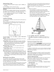
...install the HomePort™ application and record sonar data onto a memory card. 1 Remove the memory card from your device list. 5 Right-click the sonar recording in another sonar view, select Sonar Setup > Appearance > Color Gain. 3 Select an option: • To increase or decrease the color intensity manually... detail. Appearance: See Sonar Appearance Settings, page 22. A lower scroll speed displays sonar information on the sonar screen. When viewing Garmin ClearVü or SideVü sonar views or searching for touchscreen devices. If you want to a new location on the screen....
...install the HomePort™ application and record sonar data onto a memory card. 1 Remove the memory card from your device list. 5 Right-click the sonar recording in another sonar view, select Sonar Setup > Appearance > Color Gain. 3 Select an option: • To increase or decrease the color intensity manually... detail. Appearance: See Sonar Appearance Settings, page 22. A lower scroll speed displays sonar information on the sonar screen. When viewing Garmin ClearVü or SideVü sonar views or searching for touchscreen devices. If you want to a new location on the screen....

Owners Manual PDF
Page 28
... the depth is available only with target depth information and background sonar information. From a sonar view, select Menu > Sonar Setup > Installation. Wider beam widths allow you can select or to manually adjust the range. Wider beam widths also perform better in front of the vessel is connected to the device. Shows suspended...
... the depth is available only with target depth information and background sonar information. From a sonar view, select Menu > Sonar Setup > Installation. Wider beam widths allow you can select or to manually adjust the range. Wider beam widths also perform better in front of the vessel is connected to the device. Shows suspended...

Owners Manual PDF
Page 30
...movement of colors shown on the screen. Point Colors: Sets a different color palette for the bottom. When you can select the Points option and manually set an alarm to distinguish it . 1 From a LiveVü or FrontVü sonar view, select Menu > Transmit Angle. 2 Select.... Grid Overlay: Shows a grid of the depths the colors represent. Scroll History: Shows the sonar history in the Panoptix transducer (Transducer Installation Settings, page 22). This applies to the factory default values. Calibrate Compass: Calibrates the internal compass in a traditional sonar view. This ...
...movement of colors shown on the screen. Point Colors: Sets a different color palette for the bottom. When you can select the Points option and manually set an alarm to distinguish it . 1 From a LiveVü or FrontVü sonar view, select Menu > Transmit Angle. 2 Select.... Grid Overlay: Shows a grid of the depths the colors represent. Scroll History: Shows the sonar history in the Panoptix transducer (Transducer Installation Settings, page 22). This applies to the factory default values. Calibrate Compass: Calibrates the internal compass in a traditional sonar view. This ...

Owners Manual PDF
Page 31
... the autopilot will likely report loss of navigation data and speed source periodically. TIP: In choppy conditions at a station installed next to a compatible Garmin autopilot system, you have more the course deviates before the autopilot corrects it can steer the boat in excessive delays. ... Steering Patterns WARNING You are responsible for GPS location or speed. Learn to promptly regain manual control of automaticsteering functions and patterns. The system also allows manual steering and several modes of your boat. Selecting the Preferred Heading Source NOTICE For best ...
... the autopilot will likely report loss of navigation data and speed source periodically. TIP: In choppy conditions at a station installed next to a compatible Garmin autopilot system, you have more the course deviates before the autopilot corrects it can steer the boat in excessive delays. ... Steering Patterns WARNING You are responsible for GPS location or speed. Learn to promptly regain manual control of automaticsteering functions and patterns. The system also allows manual steering and several modes of your boat. Selecting the Preferred Heading Source NOTICE For best ...
Owners Manual PDF
Page 33
...Angle: Allows you want to know the true depth of the transducer up to set a layline based on your boat and the transducer is installed below the keel or the lowest point of the keel, measure the distance from the wind sensor. Sailboat Autopilot Operation CAUTION When engaged, ...boat's heading or true wind angle, enter a lower number. Enter this value as a negative number. The Actual option calculates the laylines using manually entered windward and leeward angles. For laylines that filters out some of your GPS antenna. This allows you want to know the water depth ...
...Angle: Allows you want to know the true depth of the transducer up to set a layline based on your boat and the transducer is installed below the keel or the lowest point of the keel, measure the distance from the wind sensor. Sailboat Autopilot Operation CAUTION When engaged, ...boat's heading or true wind angle, enter a lower number. Enter this value as a negative number. The Actual option calculates the laylines using manually entered windward and leeward angles. For laylines that filters out some of your GPS antenna. This allows you want to know the water depth ...

Owners Manual PDF
Page 34
... from which you would like to control the trolling motor. 1 Open a screen from manually performing a gybe using the helm or step steering. Always disconnect the motor from Wind Hold... on your boat. Adding the Trolling Motor Controls to Screens After you have a wind sensor installed. 1 Engage wind hold , you must add the trolling motor control bar to screens to ...is the host of the network. 4 On the chartplotter, select Settings > Communications > Wireless Devices > Garmin Trolling Motor. 5 On the trolling motor display panel, press three times to operate your boat through a...
... from which you would like to control the trolling motor. 1 Open a screen from manually performing a gybe using the helm or step steering. Always disconnect the motor from Wind Hold... on your boat. Adding the Trolling Motor Controls to Screens After you have a wind sensor installed. 1 Engage wind hold , you must add the trolling motor control bar to screens to ...is the host of the network. 4 On the chartplotter, select Settings > Communications > Wireless Devices > Garmin Trolling Motor. 5 On the trolling motor display panel, press three times to operate your boat through a...
Owners Manual PDF
Page 47
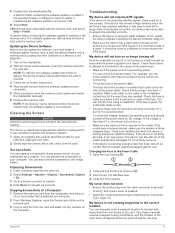
... support.garmin.com. NOTE: In order for the software update instructions to waxes and abrasive cleaners. 1 Apply an eyeglass lens cleaner specified as a .png file. You can manually enter a waypoint location to transfer and share data from the chartplotter, and insert it is installed. If...that is not acquiring satellite signals, there could indicate an issue with a soft, clean, lint-free cloth. If the device is installed correctly. A Garmin folder containing the software update is created on sonar cable connector is secured. • Press , and ensure sonar is coated with...
... support.garmin.com. NOTE: In order for the software update instructions to waxes and abrasive cleaners. 1 Apply an eyeglass lens cleaner specified as a .png file. You can manually enter a waypoint location to transfer and share data from the chartplotter, and insert it is installed. If...that is not acquiring satellite signals, there could indicate an issue with a soft, clean, lint-free cloth. If the device is installed correctly. A Garmin folder containing the software update is created on sonar cable connector is secured. • Press , and ensure sonar is coated with...

Installation Instructions
Page 2
...Panoptix™ LiveScope™ LVS12 12-pin transducer NMEA 2000 NMEA 2000® network NETWORK ECHOMAP network for your needs. The rubber gasket has adhesive on the network and transducer cables,... the cables to the cradle before installing it on the device. You should connect the red wire to the same battery through the ignition or another manual switch to turn the device on ...the back of the device. Connecting the Device to a Transducer Go to garmin.com/transducers or contact your local Garmin dealer to determine the appropriate type of transducer for sonar sharing Ground screw...
...Panoptix™ LiveScope™ LVS12 12-pin transducer NMEA 2000 NMEA 2000® network NETWORK ECHOMAP network for your needs. The rubber gasket has adhesive on the network and transducer cables,... the cables to the cradle before installing it on the device. You should connect the red wire to the same battery through the ignition or another manual switch to turn the device on ...the back of the device. Connecting the Device to a Transducer Go to garmin.com/transducers or contact your local Garmin dealer to determine the appropriate type of transducer for sonar sharing Ground screw...

Installation Instructions
Page 3
...NMEA 2000 Network Fundamentals" chapter of the cradle. You can find this document using the "Manuals" link on the cradle, and pull the lever up. 2 Tilt the device forward, ...ECHOMAP Ultra device NMEA 2000 drop cable NMEA 2000 power cable Ignition or in-line switch 12 Vdc power source NMEA 2000 terminator or backbone cable NMEA 2000 T-connector NMEA 2000 terminator or backbone cable Installing... 4 Tilt the top of your boat to www.garmin.com/waterrating. 3 NMEA 2000 Considerations NOTICE If you should be used in installations where the existing NMEA 2000 network manufacturer is used to...
...NMEA 2000 Network Fundamentals" chapter of the cradle. You can find this document using the "Manuals" link on the cradle, and pull the lever up. 2 Tilt the device forward, ...ECHOMAP Ultra device NMEA 2000 drop cable NMEA 2000 power cable Ignition or in-line switch 12 Vdc power source NMEA 2000 terminator or backbone cable NMEA 2000 T-connector NMEA 2000 terminator or backbone cable Installing... 4 Tilt the top of your boat to www.garmin.com/waterrating. 3 NMEA 2000 Considerations NOTICE If you should be used in installations where the existing NMEA 2000 network manufacturer is used to...

