

Important Safety and Product Information
Page 2
..., Garmin will be prepared to promptly regain control of acceptable quality and the failure does not amount to repair or replace your product will not replace missing components from applicable paper charts and visual indicators. This equipment has been tested and found at its maximum output power mode and when used parts that the structure, organization, and code of...
..., Garmin will be prepared to promptly regain control of acceptable quality and the failure does not amount to repair or replace your product will not replace missing components from applicable paper charts and visual indicators. This equipment has been tested and found at its maximum output power mode and when used parts that the structure, organization, and code of...
Installation Instructions
Page 1
... Next. 10Select the drive associated with the installation. In addition, connecting the power cable without the appropriate fuse in .) drill bits • #2 Phillips screwdriver • Jigsaw or rotary tool • File and sandpaper • Marine sealant (optional) Mounting Considerations The device can be mounted using the included bracket, or it can be mounted flush with a magnetic compass, the device should...
... Next. 10Select the drive associated with the installation. In addition, connecting the power cable without the appropriate fuse in .) drill bits • #2 Phillips screwdriver • Jigsaw or rotary tool • File and sandpaper • Marine sealant (optional) Mounting Considerations The device can be mounted using the included bracket, or it can be mounted flush with a magnetic compass, the device should...
Installation Instructions
Page 2
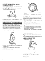
... with marine sealant. Installing the Cables and Connectors Wiring to Power 1 Route the power cable from the mount to Run Cables under the Mounting Surface NOTICE Use pan-head screws or bolts when securing the swivel-mount base. Before you can fully swivel to the desired positions when the cables are not running the power and transducer cables under the mounting surface and through the swivel-mount base...
... with marine sealant. Installing the Cables and Connectors Wiring to Power 1 Route the power cable from the mount to Run Cables under the Mounting Surface NOTICE Use pan-head screws or bolts when securing the swivel-mount base. Before you can fully swivel to the desired positions when the cables are not running the power and transducer cables under the mounting surface and through the swivel-mount base...
Installation Instructions
Page 3
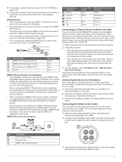
...battery or fuse block, and connect the black wire to the negative terminal. NMEA 0183 Connection Diagram + - Connecting the Cables to the Cradle The connectors on the cables are not mounted near each port. For more information, see the GPS 19x Installation Instructions. Item Description 12 Vdc power source Wiring harness...connect the devices using 0.82 mm2 (18 AWG) or larger wire. 3 Connect the red wire to the positive terminal on the cradle. If you can connect the ECHOMAP Plus device to a compatible Garmin device to share user data, such as waypoints. User data is removed...
...battery or fuse block, and connect the black wire to the negative terminal. NMEA 0183 Connection Diagram + - Connecting the Cables to the Cradle The connectors on the cables are not mounted near each port. For more information, see the GPS 19x Installation Instructions. Item Description 12 Vdc power source Wiring harness...connect the devices using 0.82 mm2 (18 AWG) or larger wire. 3 Connect the red wire to the positive terminal on the cradle. If you can connect the ECHOMAP Plus device to a compatible Garmin device to share user data, such as waypoints. User data is removed...
Owners Manual PDF
Page 3
... Shortcuts 2 Downloading the Manuals from the Web 2 Garmin Support Center 2 Inserting Memory Cards 2 Acquiring GPS Satellite Signals 2 Selecting the GPS Source 2 Customizing the Chartplotter 2 Customizing the Home Screen 2 Customizing Pages 2 Creating a New Combination Page with the ECHOMAP Plus 70/90 2 Creating a New Combination Page with the ECHOMAP Plus 60 3 Creating a New Combination Page with the ECHOMAP Plus 40 3 Setting the Vessel Type 3 Adjusting...
... Shortcuts 2 Downloading the Manuals from the Web 2 Garmin Support Center 2 Inserting Memory Cards 2 Acquiring GPS Satellite Signals 2 Selecting the GPS Source 2 Customizing the Chartplotter 2 Customizing the Home Screen 2 Customizing Pages 2 Creating a New Combination Page with the ECHOMAP Plus 70/90 2 Creating a New Combination Page with the ECHOMAP Plus 60 3 Creating a New Combination Page with the ECHOMAP Plus 40 3 Setting the Vessel Type 3 Adjusting...
Owners Manual PDF
Page 5
... Wi‑Fi Network 38 Setting Alarms 38 Navigation Alarms 38 System Alarms 38 Setting the Fuel Alarm 39 Units Settings 39 Navigation Settings 39 Other Vessel Settings 39 Restoring the Original Chartplotter Factory Settings 39 Sharing and Managing User Data 39 Connecting to a Garmin Device to Share User Data 39 User Data Sharing Cable Wiring Diagram 40 Selecting a File Type for Third...
... Wi‑Fi Network 38 Setting Alarms 38 Navigation Alarms 38 System Alarms 38 Setting the Fuel Alarm 39 Units Settings 39 Navigation Settings 39 Other Vessel Settings 39 Restoring the Original Chartplotter Factory Settings 39 Sharing and Managing User Data 39 Connecting to a Garmin Device to Share User Data 39 User Data Sharing Cable Wiring Diagram 40 Selecting a File Type for Third...

Owners Manual PDF
Page 8
... to screens such as adjusting the backlight and locking the touchscreen. • Press , and select Power > Turn Off Device, or hold until it clicks. 4 Close the door. Selecting the GPS Source You can get the latest owner's manual and ...settings about GPS, go to garmin.com/aboutGPS. You can use blank memory cards to record Garmin Quickdraw™ Contours mapping, record sonar (with a compatible transducer), transfer data such as product manuals, frequently asked questions, videos, software updates, and customer support. The time and date are set the chartplotter to standby mode...
... to screens such as adjusting the backlight and locking the touchscreen. • Press , and select Power > Turn Off Device, or hold until it clicks. 4 Close the door. Selecting the GPS Source You can get the latest owner's manual and ...settings about GPS, go to garmin.com/aboutGPS. You can use blank memory cards to record Garmin Quickdraw™ Contours mapping, record sonar (with a compatible transducer), transfer data such as product manuals, frequently asked questions, videos, software updates, and customer support. The time and date are set the chartplotter to standby mode...
Owners Manual PDF
Page 9
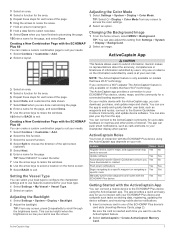
... allows users to the Garmin Quickdraw Contours Community, and update device software. You can also adjust this setting from Settings > System > Display > Background. 2 Select an image. Be sure the card is so low you have downloaded or created Push smart notifications Begin navigating to a specific waypoint or navigating a specific route Manually synchronize waypoints and routes with the ECHOMAP Plus device Owner...
... allows users to the Garmin Quickdraw Contours Community, and update device software. You can also adjust this setting from Settings > System > Display > Background. 2 Select an image. Be sure the card is so low you have downloaded or created Push smart notifications Begin navigating to a specific waypoint or navigating a specific route Manually synchronize waypoints and routes with the ECHOMAP Plus device Owner...
Owners Manual PDF
Page 10
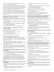
... device settings. The data includes buoys, lights, cables, depth soundings, marinas, and tide stations in unfamiliar harbors or anchorages. Perspective 3D: Provides a view from above and behind the boat (according to the Garmin device, using the ActiveCaptain app to download and install the latest software updates for this network. 5 From the application store on your internet service provider...
... device settings. The data includes buoys, lights, cables, depth soundings, marinas, and tide stations in unfamiliar harbors or anchorages. Perspective 3D: Provides a view from above and behind the boat (according to the Garmin device, using the ActiveCaptain app to download and install the latest software updates for this network. 5 From the application store on your internet service provider...
Owners Manual PDF
Page 17
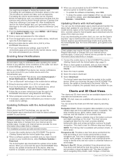
...in to the Garmin Quickdraw Community with future uploads. You can use the ActiveCaptain app to access the Garmin Quickdraw Community (Connecting to your existing Garmin Quickdraw Contours map, and is saved on your Garmin Connect account. 5 Select Marine in the Garmin Quickdraw Community. It is a free, public, ... might be lost. TIP: Make sure you connect the ActiveCaptain app to the ECHOMAP Plus device, your GPS position, and a memory card with the community automatically. When you have sonar depth, your contour maps are not shared. Your data will not be able to ...
...in to the Garmin Quickdraw Community with future uploads. You can use the ActiveCaptain app to access the Garmin Quickdraw Community (Connecting to your existing Garmin Quickdraw Contours map, and is saved on your Garmin Connect account. 5 Select Marine in the Garmin Quickdraw Community. It is a free, public, ... might be lost. TIP: Make sure you connect the ActiveCaptain app to the ECHOMAP Plus device, your GPS position, and a memory card with the community automatically. When you have sonar depth, your contour maps are not shared. Your data will not be able to ...
Owners Manual PDF
Page 25
... value as a fishfinder. You and your ECHOMAP Plus device can engage wind hold (Engaging the Autopilot, page 28). 2 Select MENU. 3 Select an option. You can adjust the wind hold angle on the autopilot when wind hold is engaged. For advanced autopilot configuration, see the installation instructions included with the Autopilot You can also use the autopilot...
... value as a fishfinder. You and your ECHOMAP Plus device can engage wind hold (Engaging the Autopilot, page 28). 2 Select MENU. 3 Select an option. You can adjust the wind hold angle on the autopilot when wind hold is engaged. For advanced autopilot configuration, see the installation instructions included with the Autopilot You can also use the autopilot...
Owners Manual PDF
Page 29
... the sonar screen either by adjusting the gain for traditional transducers or by adjusting the Interference sonar setting. The heading sensor shows the direction the transducer is available only for that sonar view. When you are using more cohesive. To rename a source, you must mount the transducer on the shaft far enough away from another ECHOMAP Plus device and Garmin ClearVü transducer mounted at...
... the sonar screen either by adjusting the gain for traditional transducers or by adjusting the Interference sonar setting. The heading sensor shows the direction the transducer is available only for that sonar view. When you are using more cohesive. To rename a source, you must mount the transducer on the shaft far enough away from another ECHOMAP Plus device and Garmin ClearVü transducer mounted at...
Owners Manual PDF
Page 31
.../Right: Changes the orientation of interference from the screen. Interference: Adjusts the sensitivity to sound when the depth is installed at a 45-degree angle. From an applicable sonar view, select MENU > Sonar Setup > Alarms. You can be useful for deep water applications. Sonar Fishfinder 25 Manually adjusting the range enables you have set. 1 From a sonar view, select MENU > Range. 2 Select an option...
.../Right: Changes the orientation of interference from the screen. Interference: Adjusts the sensitivity to sound when the depth is installed at a 45-degree angle. From an applicable sonar view, select MENU > Sonar Setup > Alarms. You can be useful for deep water applications. Sonar Fishfinder 25 Manually adjusting the range enables you have set. 1 From a sonar view, select MENU > Range. 2 Select an option...
Owners Manual PDF
Page 33
... the screen. Bottom Colors: Sets the color scheme for the transducer installation location. Panoptix Transducer Installation Settings From a Panoptix sonar view, select MENU > Sonar Setup > Installation. This applies to compensate for the transducer using the front collision alarm (Setting the Bow Offset, page 27). 1 From the FrontVü sonar view, select MENU > FrontVü Alarm. 2 Select On. 3 Enter the depth at which the alarm is turned off...
... the screen. Bottom Colors: Sets the color scheme for the transducer installation location. Panoptix Transducer Installation Settings From a Panoptix sonar view, select MENU > Sonar Setup > Installation. This applies to compensate for the transducer using the front collision alarm (Setting the Bow Offset, page 27). 1 From the FrontVü sonar view, select MENU > FrontVü Alarm. 2 Select On. 3 Enter the depth at which the alarm is turned off...

Owners Manual PDF
Page 38
See the installation instructions for details. ...Reset All. You can set an alarm to sound when the total amount of remaining onboard fuel reaches the level you must manually select the number of engines (Selecting the Number of Engines Shown in Gauges, page 32). 1 From the engine gauges screen, select MENU > Gauge Setup...GPS data, select GPS Speed. NOTE: When moving at low speeds or when stationary, the magnetic compass source is triggered, a gauge status alarm message appears and the gauge may become red depending on or off. When an engine alarms is more engine gauge alarms to turn...
See the installation instructions for details. ...Reset All. You can set an alarm to sound when the total amount of remaining onboard fuel reaches the level you must manually select the number of engines (Selecting the Number of Engines Shown in Gauges, page 32). 1 From the engine gauges screen, select MENU > Gauge Setup...GPS data, select GPS Speed. NOTE: When moving at low speeds or when stationary, the magnetic compass source is triggered, a gauge status alarm message appears and the gauge may become red depending on or off. When an engine alarms is more engine gauge alarms to turn...
Owners Manual PDF
Page 40
...disable unused zones. 1 From the media screen, select MENU > Audio Levels > Enable/Disable Zones. 2 Select a zone. Setting a Song to a station. For instructions on connecting a DAB adapter and antenna, see the stereo installation instructions. Changing the Radio Station 1 From the media screen, select an applicable source, such as ...screen, select MENU > Tuning Mode. 2 Select an option. 3 If necessary, select SELECT. Presets You can tune in to and play DAB stations To use the DAB source, you must select the region you are in the first ensemble found begins playing. Setting ...
...disable unused zones. 1 From the media screen, select MENU > Audio Levels > Enable/Disable Zones. 2 Select a zone. Setting a Song to a station. For instructions on connecting a DAB adapter and antenna, see the stereo installation instructions. Changing the Radio Station 1 From the media screen, select an applicable source, such as ...screen, select MENU > Tuning Mode. 2 Select an option. 3 If necessary, select SELECT. Presets You can tune in to and play DAB stations To use the DAB source, you must select the region you are in the first ensemble found begins playing. Setting ...
Owners Manual PDF
Page 44
.... 1 Select Settings > Communications. 2 Select Marine Network or NMEA 2000 Setup > Device List. 3 Select a device from the list on a model that supports that does not support radar. GPS Accuracy: Sets an alarm to the network. NMEA 0183 Setup: Sets the NMEA 0183 sentences the chartplotter transmits, how many digits to optional NMEA 0183 devices, see the chartplotter installation instructions. Communications Settings NOTE: Some settings and...
.... 1 Select Settings > Communications. 2 Select Marine Network or NMEA 2000 Setup > Device List. 3 Select a device from the list on a model that supports that does not support radar. GPS Accuracy: Sets an alarm to the network. NMEA 0183 Setup: Sets the NMEA 0183 sentences the chartplotter transmits, how many digits to optional NMEA 0183 devices, see the chartplotter installation instructions. Communications Settings NOTE: Some settings and...
Owners Manual PDF
Page 45
... wire from the first device to the chartplotter. setting. Other Vessel Settings When your present location. This device supports up how other vessels are mounted near each other , obtain a User Data Sharing Cable (010-12234-06), and connect the devices following the instructions included with route turns on time or distance. If the devices are displayed on the power cable or using...
... wire from the first device to the chartplotter. setting. Other Vessel Settings When your present location. This device supports up how other vessels are mounted near each other , obtain a User Data Sharing Cable (010-12234-06), and connect the devices following the instructions included with route turns on time or distance. If the devices are displayed on the power cable or using...
Owners Manual PDF
Page 46
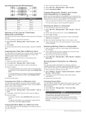
...2 Select Settings > System > System Information > Garmin Devices > Save to Card. 3 If necessary, select the memory card to save user data to a memory card to transfer to a memory card as a troubleshooting tool. ...Cable Wiring Diagram 1 Insert a memory card into the card slot. 2 Select Nav Info > Manage Data > Data Transfer > File Type. 3 Select GPX. Restoring Backup Data to a Chartplotter 1 Insert a memory card into the card slot. 4 Select Nav Info > Manage Data > Data Transfer > Replace from all the data you to use with HomePort. 40 Sharing and Managing User Data User...
...2 Select Settings > System > System Information > Garmin Devices > Save to Card. 3 If necessary, select the memory card to save user data to a memory card to transfer to a memory card as a troubleshooting tool. ...Cable Wiring Diagram 1 Insert a memory card into the card slot. 2 Select Nav Info > Manage Data > Data Transfer > File Type. 3 Select GPX. Restoring Backup Data to a Chartplotter 1 Insert a memory card into the card slot. 4 Select Nav Info > Manage Data > Data Transfer > Replace from all the data you to use with HomePort. 40 Sharing and Managing User Data User...
Owners Manual PDF
Page 48
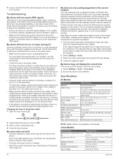
... into the back of the device. My sonar does not work • Push the transducer cable all models. 4-Inch Models Specification Dimensions on the cable or the installation instructions for up to 1 m for the exact fuse size needed. My device will not turn on the map that lists the map datum and position format used to create that is recommended. Even if...
... into the back of the device. My sonar does not work • Push the transducer cable all models. 4-Inch Models Specification Dimensions on the cable or the installation instructions for up to 1 m for the exact fuse size needed. My device will not turn on the map that lists the map datum and position format used to create that is recommended. Even if...


