Manual/User Guide
Page 1
C141-E245 3-1 CHAPTER 3 Installation Conditions 3.1 Dimensions 3.2 Mounting 3.3 Connections with Host System This chapter gives the external dimensions, installation conditions, surface temperature conditions, cable connections, and switch settings of the hard disk drives.
C141-E245 3-1 CHAPTER 3 Installation Conditions 3.1 Dimensions 3.2 Mounting 3.3 Connections with Host System This chapter gives the external dimensions, installation conditions, surface temperature conditions, cable connections, and switch settings of the hard disk drives.
Manual/User Guide
Page 2
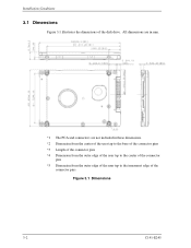
Installation Conditions 3.1 Dimensions Figure 3.1 illustrates the dimensions of the connector pins Figure 3.1 Dimensions 3-2 C141-E245 All dimensions are in mm. *1 The PCA and connectors are not included in these dimensions. *2 Dimension from the center of the user tap to the base of the connector pins *3 Length of the connector pins *4 Dimension from the outer edge of the user tap to the center of the connector pins *5 Dimension from the outer edge of the user tap to the innermost edge of the disk drive.
Installation Conditions 3.1 Dimensions Figure 3.1 illustrates the dimensions of the connector pins Figure 3.1 Dimensions 3-2 C141-E245 All dimensions are in mm. *1 The PCA and connectors are not included in these dimensions. *2 Dimension from the center of the user tap to the base of the connector pins *3 Length of the connector pins *4 Dimension from the outer edge of the user tap to the center of the connector pins *5 Dimension from the outer edge of the user tap to the innermost edge of the disk drive.
Manual/User Guide
Page 3
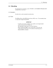
... enclosure (DE) is attached. C141-E245 3-3 The mounting frame is connected to which the HDD is zero. 3.2 Mounting 3.2 Mounting For information on mounting, see the "FUJITSU 2.5-INCH HDD INTEGRATION GUIDANCE (C141-E144)." (1) Orientation The disk drives can be 0.49N•m (5kgf•cm).
... enclosure (DE) is attached. C141-E245 3-3 The mounting frame is connected to which the HDD is zero. 3.2 Mounting 3.2 Mounting For information on mounting, see the "FUJITSU 2.5-INCH HDD INTEGRATION GUIDANCE (C141-E144)." (1) Orientation The disk drives can be 0.49N•m (5kgf•cm).
Manual/User Guide
Page 6
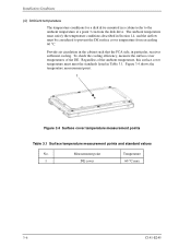
...PCA side, in Section 1.4, and the airflow must meet the standards listed in a cabinet refer to prevent the DE surface cover temperature from the disk drive. To check the cooling efficiency, measure the surface cover temperatures of the ambient temperature, this surface cover temperature must be considered to the ambient temperature.... 1 Figure 3.4 Surface cover temperature measurement points Table 3.1 Surface temperature measurement points and standard values No. Installation Conditions (4) Ambient temperature The temperature conditions for a disk drive mounted in Table 3.1.
...PCA side, in Section 1.4, and the airflow must meet the standards listed in a cabinet refer to prevent the DE surface cover temperature from the disk drive. To check the cooling efficiency, measure the surface cover temperatures of the ambient temperature, this surface cover temperature must be considered to the ambient temperature.... 1 Figure 3.4 Surface cover temperature measurement points Table 3.1 Surface temperature measurement points and standard values No. Installation Conditions (4) Ambient temperature The temperature conditions for a disk drive mounted in Table 3.1.
Manual/User Guide
Page 7
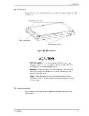
...the following cautions, and handle the HDD under the safety environment. Damage: Do not press the cover of the disk drive. C141-E245 3-7 Do not touch the printed circuit board, but hold it too hard, the cover and the spindle motor contact, which may cause damage to the disk... drive. 3.2 Mounting (5) Service area Figure 3.5 shows how the drive must be accessed (service areas) during and after installation. Mounting screw hole Cable ...
...the following cautions, and handle the HDD under the safety environment. Damage: Do not press the cover of the disk drive. C141-E245 3-7 Do not touch the printed circuit board, but hold it too hard, the cover and the spindle motor contact, which may cause damage to the disk... drive. 3.2 Mounting (5) Service area Figure 3.5 shows how the drive must be accessed (service areas) during and after installation. Mounting screw hole Cable ...
Manual/User Guide
Page 9
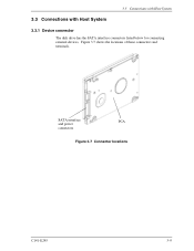
Figure 3.7 shows the locations of these connectors and terminals. SATA interface PCA and power connectors Figure 3.7 Connector locations C141-E245 3-9 3.3 Connections with Host System 3.3 Connections with Host System 3.3.1 Device connector The disk drive has the SATA interface connectors listed below for connecting external devices.
Figure 3.7 shows the locations of these connectors and terminals. SATA interface PCA and power connectors Figure 3.7 Connector locations C141-E245 3-9 3.3 Connections with Host System 3.3 Connections with Host System 3.3.1 Device connector The disk drive has the SATA interface connectors listed below for connecting external devices.
Manual/User Guide
Page 11
3.3 Connections with Host System 3.3.4 SATA interface cable connection The cable that connects the disk drive to the host system must be compliant with the Serial ATA 1.0a specification. 3.3.5 Note about SATA interface cable connection Take note of the following ...precaution about plugging a SATA interface cable into the SATA interface connector of the disk drive and plugging the connector into a host receptacle: When plugging together the disk drive SATA interface connector and the host receptacle or SATA interface cable connector, do not apply more than 10 kgf...
3.3 Connections with Host System 3.3.4 SATA interface cable connection The cable that connects the disk drive to the host system must be compliant with the Serial ATA 1.0a specification. 3.3.5 Note about SATA interface cable connection Take note of the following ...precaution about plugging a SATA interface cable into the SATA interface connector of the disk drive and plugging the connector into a host receptacle: When plugging together the disk drive SATA interface connector and the host receptacle or SATA interface cable connector, do not apply more than 10 kgf...


