Manual/User Guide
Page 1
CHAPTER 3 Installation Conditions 3.1 Dimensions 3.2 Mounting 3.3 Cable Connections 3.4 Jumper Settings This chapter gives the external dimensions, installation conditions, surface temperature conditions, cable connections, and switch settings of the hard disk drives. C141-E144 C141-E250 3-1 For information about handling this hard disk drive and the system installation procedure, refer to the following Integration Guide.
CHAPTER 3 Installation Conditions 3.1 Dimensions 3.2 Mounting 3.3 Cable Connections 3.4 Jumper Settings This chapter gives the external dimensions, installation conditions, surface temperature conditions, cable connections, and switch settings of the hard disk drives. C141-E144 C141-E250 3-1 For information about handling this hard disk drive and the system installation procedure, refer to the following Integration Guide.
Manual/User Guide
Page 6
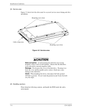
...Do not touch the printed circuit board, but hold it too hard, the cover and the spindle motor contact, which may cause damage to the disk drive. Installation Conditions (5) Service area Figure 3.5 shows how the drive must be accessed (service areas) during and after installation. Mounting ...screw hole Cable connection Mounting screw hole Figure 3.5 Service area Data corruption: Avoid mounting the disk drive near strong magnetic sources such as loud speakers. Static: When handling the device, disconnect the body ground (500 kΩ or greater)....
...Do not touch the printed circuit board, but hold it too hard, the cover and the spindle motor contact, which may cause damage to the disk drive. Installation Conditions (5) Service area Figure 3.5 shows how the drive must be accessed (service areas) during and after installation. Mounting ...screw hole Cable connection Mounting screw hole Figure 3.5 Service area Data corruption: Avoid mounting the disk drive near strong magnetic sources such as loud speakers. Static: When handling the device, disconnect the body ground (500 kΩ or greater)....


