Manual/User Guide
Page 3
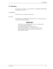
The tightening torque must be mounted in Figure 3.2. 3.2 Mounting 3.2 Mounting For information on mounting, see the "FUJITSU 2.5-INCH HDD INTEGRATION GUIDANCE (C141-E144)." (1) Orientation The disk drives can be 0.49N•m (5kgf•cm). When attaching the HDD to the system frame, do not allow the system ...frame to touch parts (cover and base) other than parts to Signal Ground (SG). Use M3 screw for the mounting screw and the screw length should satisfy the specification...
The tightening torque must be mounted in Figure 3.2. 3.2 Mounting 3.2 Mounting For information on mounting, see the "FUJITSU 2.5-INCH HDD INTEGRATION GUIDANCE (C141-E144)." (1) Orientation The disk drives can be 0.49N•m (5kgf•cm). When attaching the HDD to the system frame, do not allow the system ...frame to touch parts (cover and base) other than parts to Signal Ground (SG). Use M3 screw for the mounting screw and the screw length should satisfy the specification...
Manual/User Guide
Page 10
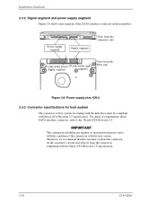
... system and select it from the PCA side Figure 3.8 Power supply pins (CN1) 3.3.3 Connector specifications for host system The connector of the connection with the Serial ATA Revision 2.5 specification. 3-10 C141-E261 For detail of the SATA interface connector and pin numbers. The connection reliability... per number of insertion/extractions varies with the condition of host system for mating with the disk drive must be compliant with Serial-ATA Revision 2.5 specification. Power supply segment Signal segment View from the connector side P1 pins in the power S1 pins in...
... system and select it from the PCA side Figure 3.8 Power supply pins (CN1) 3.3.3 Connector specifications for host system The connector of the connection with the Serial ATA Revision 2.5 specification. 3-10 C141-E261 For detail of the SATA interface connector and pin numbers. The connection reliability... per number of insertion/extractions varies with the condition of host system for mating with the disk drive must be compliant with Serial-ATA Revision 2.5 specification. Power supply segment Signal segment View from the connector side P1 pins in the power S1 pins in...
Manual/User Guide
Page 11
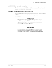
...SATA interface Latch may lead to remove the cable while releasing the Latch. Accordingly, be compliant with the Serial ATA Revision 2.5 specification. 3.3.5 Note about SATA interface cable connection Take note of the following precaution about plugging a SATA interface cable into the SATA interface... connector of the disk drive and plugging the connector into a host receptacle: When plugging together the disk drive SATA interface connector and the host receptacle or SATA interface cable connector, do not apply...
...SATA interface Latch may lead to remove the cable while releasing the Latch. Accordingly, be compliant with the Serial ATA Revision 2.5 specification. 3.3.5 Note about SATA interface cable connection Take note of the following precaution about plugging a SATA interface cable into the SATA interface... connector of the disk drive and plugging the connector into a host receptacle: When plugging together the disk drive SATA interface connector and the host receptacle or SATA interface cable connector, do not apply...
