Manual/User Guide
Page 2
... Rights Reserved, Copyright FUJITSU LIMITED 2004 IMPORTANT NOTE TO USERS READ THE ENTIRE MANUAL CAREFULLY BEFORE USING THIS PRODUCT. In addition, FUJITSU assumes no liability to as office work, personal devices and household appliances. This product is not intended for special uses (atomic controls, aeronautic or space systems, mass transport controls, medical devices for life support, or weapons firing controls) where particularly high reliability requirements...
... Rights Reserved, Copyright FUJITSU LIMITED 2004 IMPORTANT NOTE TO USERS READ THE ENTIRE MANUAL CAREFULLY BEFORE USING THIS PRODUCT. In addition, FUJITSU assumes no liability to as office work, personal devices and household appliances. This product is not intended for special uses (atomic controls, aeronautic or space systems, mass transport controls, medical devices for life support, or weapons firing controls) where particularly high reliability requirements...
Manual/User Guide
Page 5
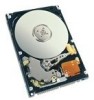
... MHV2120AT, MHV2100AT, MHV2080AT, MHV2060AT, MHV2040AT maintenance requirements, operation verification, and troubleshooting. CHAPTER 2 Removal and Replacement Procedure This chapter explains the procedure for Alert Messages This manual uses the following conventions to the product or other property may be referred to maintain the disk drives. Preface This manual describes the MHV2120AT, MHV2100AT, MHV2080AT, MHV2060AT, MHV2040AT 2.5-inch hard disk drive with the ATA interface. C141-F072 i IBM PC-AT...
... MHV2120AT, MHV2100AT, MHV2080AT, MHV2060AT, MHV2040AT maintenance requirements, operation verification, and troubleshooting. CHAPTER 2 Removal and Replacement Procedure This chapter explains the procedure for Alert Messages This manual uses the following conventions to the product or other property may be referred to maintain the disk drives. Preface This manual describes the MHV2120AT, MHV2100AT, MHV2080AT, MHV2060AT, MHV2040AT 2.5-inch hard disk drive with the ATA interface. C141-F072 i IBM PC-AT...
Manual/User Guide
Page 6
... make this manual. Preface In the text, the alert signal is centered, followed below by user misoperation or mishandling, inappropriate operating environments, defects in the power supply or cable, problems of the host system, or other disk drive defects, such as those caused by the indented message. The following is an example: (Example) Don't install or remove a PCA or connect or disconnect a cable or connector...
... make this manual. Preface In the text, the alert signal is centered, followed below by user misoperation or mishandling, inappropriate operating environments, defects in the power supply or cable, problems of the host system, or other disk drive defects, such as those caused by the indented message. The following is an example: (Example) Don't install or remove a PCA or connect or disconnect a cable or connector...
Manual/User Guide
Page 7
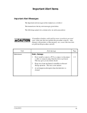
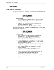
Don't install or remove a PCA or connect or disconnect 1-2 a cable or connector plug when the drive is cleaned. Avoid dangerous detergent when the disk drive is powered. The following manual also contains notes on safety precautions: Task Maintenance A hazardous situation could result in the unit during operation. Alert message Page Static, Damage 1. This may give you an electric shock. 2. This may cause...
Don't install or remove a PCA or connect or disconnect 1-2 a cable or connector plug when the drive is cleaned. Avoid dangerous detergent when the disk drive is powered. The following manual also contains notes on safety precautions: Task Maintenance A hazardous situation could result in the unit during operation. Alert message Page Static, Damage 1. This may give you an electric shock. 2. This may cause...
Manual/User Guide
Page 8
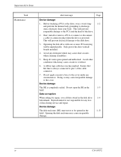
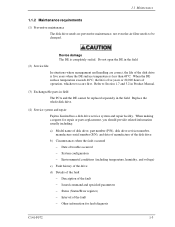
... damage to pin 1 of data during service and repair. Avoid any circumstances. Data corruption When asking for any loss of the cable connector. 7. Fujitsu Limited is always connected to the PCA and the head of the drive. 2. Opening the disk enclosure may cause circuits to be unpredictable. Don't install or remove a PCA or connect or disconnect a cable or connector plug when the drive is completely sealed. Only power the drive with one...
... damage to pin 1 of data during service and repair. Avoid any circumstances. Data corruption When asking for any loss of the cable connector. 7. Fujitsu Limited is always connected to the PCA and the head of the drive. 2. Opening the disk enclosure may cause circuits to be unpredictable. Don't install or remove a PCA or connect or disconnect a cable or connector plug when the drive is completely sealed. Only power the drive with one...
Manual/User Guide
Page 11
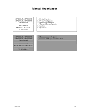
Device Overview 2. Installation Conditions 4. Manual Organization MHV2120AT, MHV2100AT MHV2080AT, MHV2060AT MHV2040AT DISK DRIVE PRODUCT MANUAL (C141-E218) 1. Interface 6. Maintenance and Diagnosis 2. Operations MHV2120AT, MHV2100AT MHV2080AT, MHV2060AT MHV2040AT DISK DRIVE MAINTENANCE MANUAL 1. Theory of Device Operation 5. Device Configuration 3. Removal and Replacement Procedure C141-F072 vii
Device Overview 2. Installation Conditions 4. Manual Organization MHV2120AT, MHV2100AT MHV2080AT, MHV2060AT MHV2040AT DISK DRIVE PRODUCT MANUAL (C141-E218) 1. Interface 6. Maintenance and Diagnosis 2. Operations MHV2120AT, MHV2100AT MHV2080AT, MHV2060AT MHV2040AT DISK DRIVE MAINTENANCE MANUAL 1. Theory of Device Operation 5. Device Configuration 3. Removal and Replacement Procedure C141-F072 vii
Manual/User Guide
Page 13
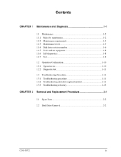
... 1-2 1.1.1 1.1.2 1.1.3 1.1.4 1.1.5 1.1.6 1.1.7 Rules for maintenance 1-2 Maintenance requirements 1-3 Maintenance levels 1-5 Disk drive revision number 1-6 Tools and test equipment 1-8 Self-diagnostics 1-8 Test...1-8 1.2 Operation Confirmation 1-10 1.2.1 Operation test 1-10 1.2.2 Diagnostic test 1-11 1.3 Troubleshooting Procedure 1-11 1.3.1 Troubleshooting procedure 1-11 1.3.2 Troubleshooting disk drive replaced in field 1-11 1.3.3 Troubleshooting at factory 1-13 CHAPTER 2 Removal and Replacement Procedure 2-1 2.1 Spare Parts 2-2 2.2 Disk Drive Removal 2-2 C141-F072 ix
... 1-2 1.1.1 1.1.2 1.1.3 1.1.4 1.1.5 1.1.6 1.1.7 Rules for maintenance 1-2 Maintenance requirements 1-3 Maintenance levels 1-5 Disk drive revision number 1-6 Tools and test equipment 1-8 Self-diagnostics 1-8 Test...1-8 1.2 Operation Confirmation 1-10 1.2.1 Operation test 1-10 1.2.2 Diagnostic test 1-11 1.3 Troubleshooting Procedure 1-11 1.3.1 Troubleshooting procedure 1-11 1.3.2 Troubleshooting disk drive replaced in field 1-11 1.3.3 Troubleshooting at factory 1-13 CHAPTER 2 Removal and Replacement Procedure 2-1 2.1 Spare Parts 2-2 2.2 Disk Drive Removal 2-2 C141-F072 ix
Manual/User Guide
Page 16
... boards installed. 4. Don't install or remove a PCA or connect or disconnect a cable or connector plug when the drive is powered. This may give you an electric shock. 2. Avoid dangerous detergent when the disk drive is always connected to discharge static electricity from mechanical assemblies in the unit during operation. This will prevent irreparable damage to the PCA and the head of the cable connector. 7. Only power the drive...
... boards installed. 4. Don't install or remove a PCA or connect or disconnect a cable or connector plug when the drive is powered. This may give you an electric shock. 2. Avoid dangerous detergent when the disk drive is always connected to discharge static electricity from mechanical assemblies in the unit during operation. This will prevent irreparable damage to the PCA and the head of the cable connector. 7. Only power the drive...
Manual/User Guide
Page 17
... information for repair or parts replacement, you should provide related information usually including: a) Model name of disk drive, part number (P/N), disk drive revision number, manufacture serial number (S/N), and date of manufacture of the disk drive b) Circumstances when the fault occurred − Date of trouble occurred − System configuration − Environmental conditions (including temperature, humidity, and voltage) c) Fault history of the drive d) Details of the fault − Description of the fault − Issued command and specified parameters...
... information for repair or parts replacement, you should provide related information usually including: a) Model name of disk drive, part number (P/N), disk drive revision number, manufacture serial number (S/N), and date of manufacture of the disk drive b) Circumstances when the fault occurred − Date of trouble occurred − System configuration − Environmental conditions (including temperature, humidity, and voltage) c) Fault history of the drive d) Details of the fault − Description of the fault − Issued command and specified parameters...
Manual/User Guide
Page 18
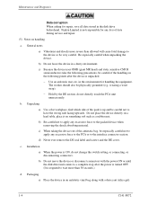
... than 30 seconds.) d. Installation a) When the power is up and be careful of data during service and repair. (5) Notes on the following precautions, be careful not to the interface connector section. in an antistatic vinyl bag along with the power ON or until the disk drive unit comes to the packed device when removing the shock absorbing material. Unpacking a) Use a flat workplace, find...
... than 30 seconds.) d. Installation a) When the power is up and be careful of data during service and repair. (5) Notes on the following precautions, be careful not to the interface connector section. in an antistatic vinyl bag along with the power ON or until the disk drive unit comes to the packed device when removing the shock absorbing material. Unpacking a) Use a flat workplace, find...
Manual/User Guide
Page 19
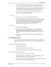
... sudden changes of temperature. 1.1.3 Maintenance levels Because of the MHV2120AT, MHV2100AT, MHV2080AT, MHV2060AT, MHV2040AT Disk Drives Product Manual. Storage a) Store in either of box, adequately protect the PCA surface and interface connector section. This section describes maintenance on the outside of the MHV2120AT, MHV2100AT, MHV2080AT, MHV2060AT, MHV2040AT Disk Drives Product Manual. Deliver an unpacked device in dampproof packaging. This includes recommended spare parts and repairing or replacing various parts...
... sudden changes of temperature. 1.1.3 Maintenance levels Because of the MHV2120AT, MHV2100AT, MHV2080AT, MHV2060AT, MHV2040AT Disk Drives Product Manual. Storage a) Store in either of box, adequately protect the PCA surface and interface connector section. This section describes maintenance on the outside of the MHV2120AT, MHV2100AT, MHV2080AT, MHV2060AT, MHV2040AT Disk Drives Product Manual. Deliver an unpacked device in dampproof packaging. This includes recommended spare parts and repairing or replacing various parts...
Manual/User Guide
Page 20
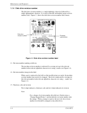
... 4-digit indicates a firmware code and rest 4-digit indicates its revision. Disk drive revision number Firmware code/revision Figure 1.1 Disk drive revision number label (1) Revision number marking at delivery The machine revision number is indicated by crossing out up to the relevant number in the relevant alphabetic character row using ¡ marks (see Figure 1.2). (2) Revision number change in the field When a part is made , the machine revision number may need to be changed...
... 4-digit indicates a firmware code and rest 4-digit indicates its revision. Disk drive revision number Firmware code/revision Figure 1.1 Disk drive revision number label (1) Revision number marking at delivery The machine revision number is indicated by crossing out up to the relevant number in the relevant alphabetic character row using ¡ marks (see Figure 1.2). (2) Revision number change in the field When a part is made , the machine revision number may need to be changed...
Manual/User Guide
Page 22
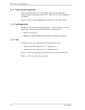
... manual. 1.1.6 Self-diagnostics The disk drive has the following three levels. • Operating test (See Subsection 1.2.1, "Operating test.") • Diagnostic test (See Subsection 1.2.2, "Diagnostic test.") Figure 1.3 shows the relationship between the test level and troubleshooting. Maintenance and Diagnosis 1.1.5 Tools and test equipment At the field maintenance level, only ordinary hand tools are beyond the scope of an isolated disk drive can be checked. • Initial self-diagnostics • SMART command (SMART...
... manual. 1.1.6 Self-diagnostics The disk drive has the following three levels. • Operating test (See Subsection 1.2.1, "Operating test.") • Diagnostic test (See Subsection 1.2.2, "Diagnostic test.") Figure 1.3 shows the relationship between the test level and troubleshooting. Maintenance and Diagnosis 1.1.5 Tools and test equipment At the field maintenance level, only ordinary hand tools are beyond the scope of an isolated disk drive can be checked. • Initial self-diagnostics • SMART command (SMART...
Manual/User Guide
Page 24
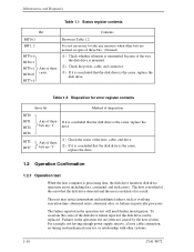
... operation test will need further investigation. Failures in Table 1.2 It is not necessary to take any measure when other systems. 1-10 C141-F072 Shown in the operation test are "1". The host is notified of the host, cable, and drive. (2) If it is concluded that the disk drive detected and the user is processing data, the disk drive monitors disk drive operation errors including data, command, and seek errors. Any of these cases. The failure...
... operation test will need further investigation. Failures in Table 1.2 It is not necessary to take any measure when other systems. 1-10 C141-F072 Shown in the operation test are "1". The host is notified of the host, cable, and drive. (2) If it is concluded that the disk drive detected and the user is processing data, the disk drive monitors disk drive operation errors including data, command, and seek errors. Any of these cases. The failure...
Manual/User Guide
Page 25
... burnt parts on the test equipment used in maintenance of failure is elsewhere in the test at the user site to isolate the reported failure to check the disk drive performance. The test is usually performed by replacing the disk drive, try to separate the fault from the other sections of the disk drive host system. 1.2.2 Diagnostic test The diagnostic test is tested using another host computer or test equipment. The procedures used . System level troubleshooting...
... burnt parts on the test equipment used in maintenance of failure is elsewhere in the test at the user site to isolate the reported failure to check the disk drive performance. The test is usually performed by replacing the disk drive, try to separate the fault from the other sections of the disk drive host system. 1.2.2 Diagnostic test The diagnostic test is tested using another host computer or test equipment. The procedures used . System level troubleshooting...
Manual/User Guide
Page 26
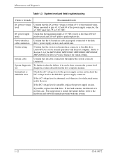
..., MHV2080AT, MHV2060AT, MHV2040AT Disk Drives Product Manual for normal operation with the system. 1-12 C141-F072 If the fault remains, the disk drive is unstable, replace the power supply section. Maintenance and Diagnosis Table 1.3 System level and field troubleshooting Check to be made Recommended work DC power voltage level DC power ripple noise Power-interface cable connection Switch setting System cable System diagnostic test Intermittent or indefinite error Confirm that the DC power voltage is within ±...
..., MHV2080AT, MHV2060AT, MHV2040AT Disk Drives Product Manual for normal operation with the system. 1-12 C141-F072 If the fault remains, the disk drive is unstable, replace the power supply section. Maintenance and Diagnosis Table 1.3 System level and field troubleshooting Check to be made Recommended work DC power voltage level DC power ripple noise Power-interface cable connection Switch setting System cable System diagnostic test Intermittent or indefinite error Confirm that the DC power voltage is within ±...
Manual/User Guide
Page 27
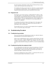
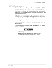
... normal test, the reappearance test is connected to the subassembly parts. At the factory, user environment is made by a factory, this manual. C141-F072 1-13 If no trouble occurs by replacing the drive at field (Subsection 1.3.2), troubleshoot the replaced drive to isolate the trouble to the host system. Device damage The disk enclosure (DE) must never to repair. Opening the disk enclosure may cause irreparable damage. To shorten the troubleshooting time and repairing time, gather the data...
... normal test, the reappearance test is connected to the subassembly parts. At the factory, user environment is made by a factory, this manual. C141-F072 1-13 If no trouble occurs by replacing the drive at field (Subsection 1.3.2), troubleshoot the replaced drive to isolate the trouble to the host system. Device damage The disk enclosure (DE) must never to repair. Opening the disk enclosure may cause irreparable damage. To shorten the troubleshooting time and repairing time, gather the data...
Manual/User Guide
Page 30
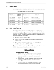
... that attach the drive and remove the drive from damage and prevent the worker getting hurt, observe the following cautions and precautions in compliance with notes, are as follows. a) Disconnect the power-interface cable. Table 2.1 Model and parts numbers Model Name MHV2120AT MHV2100AT MHV2080AT MHV2060AT MHV2040AT Capacity (user area) 120GB 100GB 80GB 60GB 40GB Mounting screw Order No. Removal and Replacement Procedure 2.1 Spare Parts See Table...
... that attach the drive and remove the drive from damage and prevent the worker getting hurt, observe the following cautions and precautions in compliance with notes, are as follows. a) Disconnect the power-interface cable. Table 2.1 Model and parts numbers Model Name MHV2120AT MHV2100AT MHV2080AT MHV2060AT MHV2040AT Capacity (user area) 120GB 100GB 80GB 60GB 40GB Mounting screw Order No. Removal and Replacement Procedure 2.1 Spare Parts See Table...
Manual/User Guide
Page 31
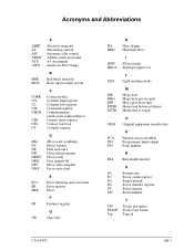
... current Disk enclosure Device/head register Drive ready Data request bit Drive seek complete Drive write fault E ECC Error checking and correction ER Error register ERR Error F FR Features register G GB Giga byte HA HDD H Host adapter Hard disk drive IDNF IRQ14 I ID not found Interrupt request 14 L LED Light emitting diode MB MB/s MPU MTBF MTTR M Mega-byte Mega-byte per seconds Micro processor unit Mean time between failures Mean time to repair...
... current Disk enclosure Device/head register Drive ready Data request bit Drive seek complete Drive write fault E ECC Error checking and correction ER Error register ERR Error F FR Features register G GB Giga byte HA HDD H Host adapter Hard disk drive IDNF IRQ14 I ID not found Interrupt request 14 L LED Light emitting diode MB MB/s MPU MTBF MTTR M Mega-byte Mega-byte per seconds Micro processor unit Mean time between failures Mean time to repair...
Manual/User Guide
Page 33
...general 1-4 on handling 1-4 O Offline self-diagnostics 1-8 Operation configuration 1-10 test 1-10 P Packaging 1-4 dampproof 1-5 Part number 2-2 replacement 1-5 Preventive maintenance 1-3 R Removal and replacement procedure 2-1 Revision, firmware code 1-6 Revision number change in field 1-6, 1-7 mark when delivered 1-6, 1-7 Rule for maintenance 1-2 S Self-diagnostics 1-8 initial 1-8 offline 1-8 Service life 1-3 system and repair 1-3 Spare part 2-2 Status register contents 1-10 Storage 1-5 System level 1-12 and field troubleshooting 1-12 T Test 1-8 equipment 1-8 flowchart 1-9 Tool 1-8 C141-F072...
...general 1-4 on handling 1-4 O Offline self-diagnostics 1-8 Operation configuration 1-10 test 1-10 P Packaging 1-4 dampproof 1-5 Part number 2-2 replacement 1-5 Preventive maintenance 1-3 R Removal and replacement procedure 2-1 Revision, firmware code 1-6 Revision number change in field 1-6, 1-7 mark when delivered 1-6, 1-7 Rule for maintenance 1-2 S Self-diagnostics 1-8 initial 1-8 offline 1-8 Service life 1-3 system and repair 1-3 Spare part 2-2 Status register contents 1-10 Storage 1-5 System level 1-12 and field troubleshooting 1-12 T Test 1-8 equipment 1-8 flowchart 1-9 Tool 1-8 C141-F072...


