Manual/User Guide
Page 5
...the external dimensions, installation conditions, and switch settings of the disk drive. CHAPTER 6 Operations This chapter describes the operations of the systems in this manual. These drives have a built-in controller that the reader has a basic knowledge of hard disk drives and their... disk drive and describes their features. CHAPTER 2 Device Configuration This chapter describes the internal configurations of the disk drive and the configuration of the disk drive. Preface This manual describes MHT2080AT/ MHT2060AT/ MHT2040AT/ MHT2030AT/ MHT2020AT models of the disk drive. CHAPTER...
...the external dimensions, installation conditions, and switch settings of the disk drive. CHAPTER 6 Operations This chapter describes the operations of the systems in this manual. These drives have a built-in controller that the reader has a basic knowledge of hard disk drives and their... disk drive and describes their features. CHAPTER 2 Device Configuration This chapter describes the internal configurations of the disk drive and the configuration of the disk drive. Preface This manual describes MHT2080AT/ MHT2060AT/ MHT2040AT/ MHT2030AT/ MHT2020AT models of the disk drive. CHAPTER...
Manual/User Guide
Page 14
Contents CHAPTER 3 Installation Conditions 3-1 3.1 Dimensions 3-2 3.2 Mounting 3-3 3.3 Cable Connections 3-9 3.3.1 Device connector 3-9 3.3.2 Cable connector specifications 3-10 3.3.3 Device connection 3-10 3.3.4 Power supply connector (CN1 3-11 3.4 Jumper Settings 3-11 3.4.1 Location of setting jumpers 3-11 3.4.2 Factory default setting 3-12 3.4.3 Master drive-slave drive setting 3-12 3.4.4 CSEL setting 3-13 3.4.5 Power Up in Standby setting 3-14 CHAPTER 4 Theory of Device Operation...
Contents CHAPTER 3 Installation Conditions 3-1 3.1 Dimensions 3-2 3.2 Mounting 3-3 3.3 Cable Connections 3-9 3.3.1 Device connector 3-9 3.3.2 Cable connector specifications 3-10 3.3.3 Device connection 3-10 3.3.4 Power supply connector (CN1 3-11 3.4 Jumper Settings 3-11 3.4.1 Location of setting jumpers 3-11 3.4.2 Factory default setting 3-12 3.4.3 Master drive-slave drive setting 3-12 3.4.4 CSEL setting 3-13 3.4.5 Power Up in Standby setting 3-14 CHAPTER 4 Theory of Device Operation...
Manual/User Guide
Page 18
... turned off 1-6 Figure 1.2 Current fluctuation (Typ.) at +5 V when power is turned on 1-8 Figure 2.1 Disk drive outerview 2-2 Figure 2.2 1 drive system configuration 2-3 Figure 2.3 2 drives configuration 2-4 Figure 3.1 Dimensions 3-2 Figure 3.2 Orientation 3-3 Figure 3.3 Mounting frame structure 3-4 Figure 3.4 Location of breather 3-5 Figure 3.5 Surface temperature...11 Jumper location 3-11 Figure 3.12 Factory default setting 3-12 Figure 3.13 Jumper setting of master or slave drive 3-12 Figure 3.14 CSEL setting 3-13 Figure 3.15 Example (1) of Cable Select 3-13 Figure 3.16 Example...
... turned off 1-6 Figure 1.2 Current fluctuation (Typ.) at +5 V when power is turned on 1-8 Figure 2.1 Disk drive outerview 2-2 Figure 2.2 1 drive system configuration 2-3 Figure 2.3 2 drives configuration 2-4 Figure 3.1 Dimensions 3-2 Figure 3.2 Orientation 3-3 Figure 3.3 Mounting frame structure 3-4 Figure 3.4 Location of breather 3-5 Figure 3.5 Surface temperature...11 Jumper location 3-11 Figure 3.12 Factory default setting 3-12 Figure 3.13 Jumper setting of master or slave drive 3-12 Figure 3.14 CSEL setting 3-13 Figure 3.15 Example (1) of Cable Select 3-13 Figure 3.16 Example...
Manual/User Guide
Page 24
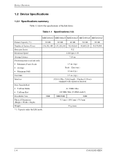
...Rotational Speed Average Latency Positioning time (read and seek) • Minimum (Track-Track) • Average • Maximum (Full) 80 GB 60 GB 40 GB 30 GB 156,301,488 117,210,240 78,140,160 58,605,120 512 4,200 rpm ± 1% 7.14 ms 1.5 ms (typ...ATA-6 (Max. Table 1.1 Specifications (1/2) MHT2080AT MHT2060AT MHT2040AT MHT2030AT MHT2020AT Format Capacity (*1) Number of the disk drives. Cable length: 18inches (0.46 m)) (equipped with expansion function) 41.3 MB/s Max. 100 MB/s Max (U-DMA mode5) Data Buffer Size Physical Dimensions (Height × Width × Depth) Weight *1: ...
...Rotational Speed Average Latency Positioning time (read and seek) • Minimum (Track-Track) • Average • Maximum (Full) 80 GB 60 GB 40 GB 30 GB 156,301,488 117,210,240 78,140,160 58,605,120 512 4,200 rpm ± 1% 7.14 ms 1.5 ms (typ...ATA-6 (Max. Table 1.1 Specifications (1/2) MHT2080AT MHT2060AT MHT2040AT MHT2030AT MHT2020AT Format Capacity (*1) Number of the disk drives. Cable length: 18inches (0.46 m)) (equipped with expansion function) 41.3 MB/s Max. 100 MB/s Max (U-DMA mode5) Data Buffer Size Physical Dimensions (Height × Width × Depth) Weight *1: ...
Manual/User Guide
Page 39
C141-E144 C141-E192-02EN 3-1 CHAPTER 3 Installation Conditions 3.1 Dimensions 3.2 Mounting 3.3 Cable Connections 3.4 Jumper Settings This chapter gives the external dimensions, installation conditions, surface temperature conditions, cable connections, and switch settings of the hard disk drives. For information about handling this hard disk drive and the system installation procedure, refer to the following Integration Guide.
C141-E144 C141-E192-02EN 3-1 CHAPTER 3 Installation Conditions 3.1 Dimensions 3.2 Mounting 3.3 Cable Connections 3.4 Jumper Settings This chapter gives the external dimensions, installation conditions, surface temperature conditions, cable connections, and switch settings of the hard disk drives. For information about handling this hard disk drive and the system installation procedure, refer to the following Integration Guide.

Manual/User Guide
Page 40
All dimensions are in mm. Figure 3.1 Dimensions 3-2 C141-E192-02EN Installation Conditions 3.1 Dimensions Figure 3.1 illustrates the dimensions of the disk drive and positions of the mounting screw holes.
All dimensions are in mm. Figure 3.1 Dimensions 3-2 C141-E192-02EN Installation Conditions 3.1 Dimensions Figure 3.1 illustrates the dimensions of the disk drive and positions of the mounting screw holes.
Manual/User Guide
Page 42
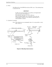
... parts (cover and base) other than parts to which the HDD is not possible to SG. if it is attached. (3) Limitation of mounting Note) These dimensions are recommended values; Installation Conditions (2) Frame The MR head bias of the HDD disk enclosure (DE) is connected to satisfy them, contact us. The mounting...
... parts (cover and base) other than parts to which the HDD is not possible to SG. if it is attached. (3) Limitation of mounting Note) These dimensions are recommended values; Installation Conditions (2) Frame The MR head bias of the HDD disk enclosure (DE) is connected to satisfy them, contact us. The mounting...