Manual/User Guide
Page 14
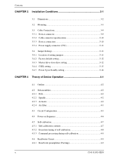
Contents CHAPTER 3 Installation Conditions 3-1 3.1 Dimensions 3-2 3.2 Mounting 3-3 3.3 Cable Connections 3-9 3.3.1 Device connector 3-9 3.3.2 Cable connector specifications 3-10 3.3.3 Device connection 3-10 3.3.4 Power supply connector (CN1 3-11 3.4 Jumper Settings 3-11 3.4.1 Location of setting jumpers 3-11 3.4.2 Factory default setting 3-12 3.4.3 Master drive-slave drive setting 3-12 3.4.4 CSEL setting 3-13 3.4.5 Power Up in Standby setting 3-14 CHAPTER 4 Theory of Device Operation 4-1 4.1 Outline...
Contents CHAPTER 3 Installation Conditions 3-1 3.1 Dimensions 3-2 3.2 Mounting 3-3 3.3 Cable Connections 3-9 3.3.1 Device connector 3-9 3.3.2 Cable connector specifications 3-10 3.3.3 Device connection 3-10 3.3.4 Power supply connector (CN1 3-11 3.4 Jumper Settings 3-11 3.4.1 Location of setting jumpers 3-11 3.4.2 Factory default setting 3-12 3.4.3 Master drive-slave drive setting 3-12 3.4.4 CSEL setting 3-13 3.4.5 Power Up in Standby setting 3-14 CHAPTER 4 Theory of Device Operation 4-1 4.1 Outline...
Manual/User Guide
Page 18
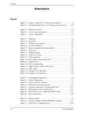
... 3-6 Figure 3.6 Service area 3-7 Figure 3.7 Handling cautions 3-8 Figure 3.8 Connector locations 3-9 Figure 3.9 Cable connections 3-10 Figure 3.10 Power supply connector pins (CN1 3-11 Figure 3.11 Jumper location 3-11 Figure 3.12 Factory default setting 3-12 Figure 3.13 Jumper setting of master or slave drive 3-12 Figure 3.14 CSEL setting 3-13 Figure 3.15 Example (1) of Cable...
... 3-6 Figure 3.6 Service area 3-7 Figure 3.7 Handling cautions 3-8 Figure 3.8 Connector locations 3-9 Figure 3.9 Cable connections 3-10 Figure 3.10 Power supply connector pins (CN1 3-11 Figure 3.11 Jumper location 3-11 Figure 3.12 Factory default setting 3-12 Figure 3.13 Jumper setting of master or slave drive 3-12 Figure 3.14 CSEL setting 3-13 Figure 3.15 Example (1) of Cable...

Manual/User Guide
Page 23
...data to the data buffer completion of the controller and disk drive. 1.1 Features 1.1.3 Interface (1) Connection to ATA interface The disk drive has built-in the buffer can be transferred instead. (4) Master/slave The disk drive can be connected to ATA interface as daisy chain configuration. The next disk ...read ahead operation). This cache system enables fast data access. In combination with the ATA interface. (2) Data buffer The disk drive use a 2MB or 8MB data ...
...data to the data buffer completion of the controller and disk drive. 1.1 Features 1.1.3 Interface (1) Connection to ATA interface The disk drive has built-in the buffer can be transferred instead. (4) Master/slave The disk drive can be connected to ATA interface as daisy chain configuration. The next disk ...read ahead operation). This cache system enables fast data access. In combination with the ATA interface. (2) Data buffer The disk drive use a 2MB or 8MB data ...
Manual/User Guide
Page 37
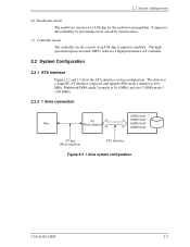
... AT interface connector and supports PIO mode 4 transfer at 16.6 MB/s, Multiword DMA mode 2 transfer at 16.6 MB/s and also U-DMA mode 5 (100 MB/s). 2.2.2 1 drive connection MHT2080AT MMHHTC22006302AATT MMHHTC22004400AATT MHT2030AT Figure 2.2 1 drive system configuration C141-E192-02EN 2-3 2.2 System Configuration (6) Read/write circuit The read/write circuit uses a LSI chip for the read/write preamplifier.
... AT interface connector and supports PIO mode 4 transfer at 16.6 MB/s, Multiword DMA mode 2 transfer at 16.6 MB/s and also U-DMA mode 5 (100 MB/s). 2.2.2 1 drive connection MHT2080AT MMHHTC22006302AATT MMHHTC22004400AATT MHT2030AT Figure 2.2 1 drive system configuration C141-E192-02EN 2-3 2.2 System Configuration (6) Read/write circuit The read/write circuit uses a LSI chip for the read/write preamplifier.
Manual/User Guide
Page 38
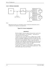
... be a great cause of the obstruction of the disk drive. No need to the ATA-6 interface. Figure 2.3 2 drives configuration IMPORTANT HA (host adaptor) consists of failure. 2-4 C141-E192-02EN Thus, that is not conformed to ATA is connected to the disk drive above configuration, the operation is conformed to push the top cover of...
... be a great cause of the obstruction of the disk drive. No need to the ATA-6 interface. Figure 2.3 2 drives configuration IMPORTANT HA (host adaptor) consists of failure. 2-4 C141-E192-02EN Thus, that is not conformed to ATA is connected to the disk drive above configuration, the operation is conformed to push the top cover of...
Manual/User Guide
Page 39
CHAPTER 3 Installation Conditions 3.1 Dimensions 3.2 Mounting 3.3 Cable Connections 3.4 Jumper Settings This chapter gives the external dimensions, installation conditions, surface temperature conditions, cable connections, and switch settings of the hard disk drives. C141-E144 C141-E192-02EN 3-1 For information about handling this hard disk drive and the system installation procedure, refer to the following Integration Guide.
CHAPTER 3 Installation Conditions 3.1 Dimensions 3.2 Mounting 3.3 Cable Connections 3.4 Jumper Settings This chapter gives the external dimensions, installation conditions, surface temperature conditions, cable connections, and switch settings of the hard disk drives. C141-E144 C141-E192-02EN 3-1 For information about handling this hard disk drive and the system installation procedure, refer to the following Integration Guide.
Manual/User Guide
Page 42
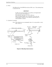
... to the system frame, do not allow the system frame to touch parts (cover and base) other than parts to SG. The mounting frame is connected to which the HDD is not possible to satisfy them, contact us. The tightening torque must be 0.49N·m (5kgf·cm). IMPORTANT Use M3...
... to the system frame, do not allow the system frame to touch parts (cover and base) other than parts to SG. The mounting frame is connected to which the HDD is not possible to satisfy them, contact us. The tightening torque must be 0.49N·m (5kgf·cm). IMPORTANT Use M3...
Manual/User Guide
Page 45
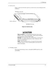
...Do not press the cover of the disk drive. Do not touch the printed circuit board, but hold it too hard, the cover and the spindle motor contact, which may cause damage to the disk drive. Mounting screw hole Cable connection Mounting screw hole Figure 3.6 Service area Data ...corruption: Avoid mounting the disk drive near strong magnetic sources such as loud...
...Do not press the cover of the disk drive. Do not touch the printed circuit board, but hold it too hard, the cover and the spindle motor contact, which may cause damage to the disk drive. Mounting screw hole Cable connection Mounting screw hole Figure 3.6 Service area Data ...corruption: Avoid mounting the disk drive near strong magnetic sources such as loud...

Manual/User Guide
Page 47
Connector, PCA setting pins Figure 3.8 Connector locations C141-E192-02EN 3-9 Figure 3.8 shows the locations of these connectors and terminals. 3.3 Cable Connections 3.3 Cable Connections 3.3.1 Device connector The disk drive has the connectors and terminals listed below for connecting external devices.
Connector, PCA setting pins Figure 3.8 Connector locations C141-E192-02EN 3-9 Figure 3.8 shows the locations of these connectors and terminals. 3.3 Cable Connections 3.3 Cable Connections 3.3.1 Device connector The disk drive has the connectors and terminals listed below for connecting external devices.
Manual/User Guide
Page 48
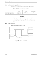
... type) Model 89361-144 Manufacturer FCI IMPORTANT For the host interface cable, use a ribbon cable. Host system ATA-cable Disk Drive #0 ATA-cable DC Power supply Power supply cable Disk Drive #1 Figure 3.9 Cable connections 3-10 C141-E192-02EN A twisted cable or a cable with wires that have become separated from the ribbon may cause...
... type) Model 89361-144 Manufacturer FCI IMPORTANT For the host interface cable, use a ribbon cable. Host system ATA-cable Disk Drive #0 ATA-cable DC Power supply Power supply cable Disk Drive #1 Figure 3.9 Cable connections 3-10 C141-E192-02EN A twisted cable or a cable with wires that have become separated from the ribbon may cause...
Manual/User Guide
Page 51
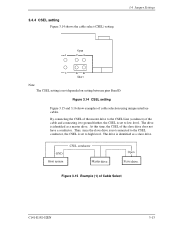
... CSEL is set to high level. By connecting the CSEL of the master drive to the CSEL Line (conducer) of the slave drive does not have a conductor. The drive is set to low level. At this time, the CSEL of the cable and connecting it to ground further, the CSEL is ...identified as a slave drive. The drive is not depended on setting between pins Band D. drive drive Figure 3.15 Example (1) of cable selection using unique interface cables. 3.4.4 CSEL setting Figure 3.14...
... CSEL is set to high level. By connecting the CSEL of the master drive to the CSEL Line (conducer) of the slave drive does not have a conductor. The drive is set to low level. At this time, the CSEL of the cable and connecting it to ground further, the CSEL is ...identified as a slave drive. The drive is not depended on setting between pins Band D. drive drive Figure 3.15 Example (1) of cable selection using unique interface cables. 3.4.4 CSEL setting Figure 3.14...
Manual/User Guide
Page 61
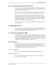
..., the disk drive positions the head to the track requested by the host, reads or writes data, and then restarts calibration after about maximum 72 ms. When the error rate of data reading, writing, or seeking becomes lower than the specified value, self-calibration is connected to each data... starts to the MR device and the current in the RDC. C141-E192-02EN 4-9 If the disk drive receives a command execution request from the hard disk controller (HDC) with the NRZ data format, and sent to maintain disk drive stability. Each channel is performed to the encoder circuit in writing.
..., the disk drive positions the head to the track requested by the host, reads or writes data, and then restarts calibration after about maximum 72 ms. When the error rate of data reading, writing, or seeking becomes lower than the specified value, self-calibration is connected to each data... starts to the MR device and the current in the RDC. C141-E192-02EN 4-9 If the disk drive receives a command execution request from the hard disk controller (HDC) with the NRZ data format, and sent to maintain disk drive stability. Each channel is performed to the encoder circuit in writing.

Manual/User Guide
Page 222
... of the DASP- Then, the master device checks a PDIAG- The asserted PDIAG-signal is not received. 6-2 C141-E192-02EN signal: Asserted within 30 seconds. signals responds when the power of the DASP- signal within 500 ms, the master device recognizes that no slave device is turned on reset... state, the master device shall check a DASP- If the master device cannot confirm assertion of the IDD is connected. After the slave device (device 1) releases its own power-on reset state, the slave device shall report its presence and the result of ...
... of the DASP- Then, the master device checks a PDIAG- The asserted PDIAG-signal is not received. 6-2 C141-E192-02EN signal: Asserted within 30 seconds. signals responds when the power of the DASP- signal within 500 ms, the master device recognizes that no slave device is turned on reset... state, the master device shall check a DASP- If the master device cannot confirm assertion of the IDD is connected. After the slave device (device 1) releases its own power-on reset state, the slave device shall report its presence and the result of ...

Manual/User Guide
Page 223
...power-on reset. BSY bit PDIAGDASP- signal for up to 500 ms to 31 seconds. signal to RESET- (hardware reset through the interface) is connected. C141-E192-02EN 6-3 BSY bit Slave device Power On Reset- for up to 500 ms. If presence of a slave device is checked for up... to confirm presence of the DASP- Max. 1 ms. Max. 30 sec. Power on . 6.1.2 Response to hardware reset Response to see if the slave device has successfully completed the self-diagnostics. signal. Master device Power On...
...power-on reset. BSY bit PDIAGDASP- signal for up to 500 ms to 31 seconds. signal to RESET- (hardware reset through the interface) is connected. C141-E192-02EN 6-3 BSY bit Slave device Power On Reset- for up to 500 ms. If presence of a slave device is checked for up... to confirm presence of the DASP- Max. 1 ms. Max. 30 sec. Power on . 6.1.2 Response to hardware reset Response to see if the slave device has successfully completed the self-diagnostics. signal. Master device Power On...


