Manual/User Guide
Page 37
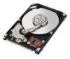
... "AT attachment". No need to the ATA-5 interface. The disk drive is an abbreviation of failure. 2.2 System Configuration IMPORTANT HA (host adaptor) consists of the disk drive. ATA is conformed to push the top cover of address decoder, driver, and receiver. If the over-power worked, the cover could be... a great cause of the obstruction of the signal lines (AT bus) between the HA and the disk drive should be contacted with...
... "AT attachment". No need to the ATA-5 interface. The disk drive is an abbreviation of failure. 2.2 System Configuration IMPORTANT HA (host adaptor) consists of the disk drive. ATA is conformed to push the top cover of address decoder, driver, and receiver. If the over-power worked, the cover could be... a great cause of the obstruction of the signal lines (AT bus) between the HA and the disk drive should be contacted with...

Manual/User Guide
Page 46
... the screw strictly. Recommended equipments ESD Shock Contents Wrist strap ESD mat Low shock driver Model JX-1200-3056-8 SKY-8A (Color Seiden Mat) SS-6500 Maker SUMITOMO 3M Achilles HIOS 3-8 C141-E120-02EN Do not hit HDD each other. ... on the operation table, and place ESD mat on it. M3 0.49 N·m (5 Kg·cm) - HDD is occasionally damaged by the impact of the driver. (2) Please observe the tightening torque of a low impact when you use an electric...
... the screw strictly. Recommended equipments ESD Shock Contents Wrist strap ESD mat Low shock driver Model JX-1200-3056-8 SKY-8A (Color Seiden Mat) SS-6500 Maker SUMITOMO 3M Achilles HIOS 3-8 C141-E120-02EN Do not hit HDD each other. ... on the operation table, and place ESD mat on it. M3 0.49 N·m (5 Kg·cm) - HDD is occasionally damaged by the impact of the driver. (2) Please observe the tightening torque of a low impact when you use an electric...

Manual/User Guide
Page 56
Theory of Device Operation 4.3 Circuit Configuration Figure 4.2 shows the power supply configuration of the disk drive, and Figure 4.3 shows the disk drive circuit configuration. (1) Read/write circuit The read/write circuit consists of a motor and controls the motor speed comparing target speed... coil motor. The servo information is the read demodulation circuit using the servo information recorded on the media surface. (3) Spindle motor driver circuit The circuit measures the interval of a PHASE signal generated by counterelectromotive voltage of two LSIs; The RDC is an analog signal...
Theory of Device Operation 4.3 Circuit Configuration Figure 4.2 shows the power supply configuration of the disk drive, and Figure 4.3 shows the disk drive circuit configuration. (1) Read/write circuit The read/write circuit consists of a motor and controls the motor speed comparing target speed... coil motor. The servo information is the read demodulation circuit using the servo information recorded on the media surface. (3) Spindle motor driver circuit The circuit measures the interval of a PHASE signal generated by counterelectromotive voltage of two LSIs; The RDC is an analog signal...
Manual/User Guide
Page 67
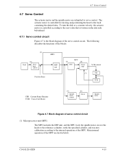
...motor, moves the heads to the reference cylinders, seeks the specified cylinder, and executes calibration according to servo control. C141-E120-02EN 4-15 The following describes the functions of the blocks: (1) Head (2) Servo burst capture MPU DSP unit Position Sense SVC (3) DAC (4) Power... Amp VCM current (7) CSR VCM CSR: Current Sense Resister VCM: Voice Coil Motor (5) Spindle motor control (6) Driver Spindle motor Figure 4.7 Block diagram of the servo control circuit. 4.7 Servo Control 4.7 Servo Control The actuator motor and the spindle motor are...
...motor, moves the heads to the reference cylinders, seeks the specified cylinder, and executes calibration according to servo control. C141-E120-02EN 4-15 The following describes the functions of the blocks: (1) Head (2) Servo burst capture MPU DSP unit Position Sense SVC (3) DAC (4) Power... Amp VCM current (7) CSR VCM CSR: Current Sense Resister VCM: Voice Coil Motor (5) Spindle motor control (6) Driver Spindle motor Figure 4.7 Block diagram of the servo control circuit. 4.7 Servo Control 4.7 Servo Control The actuator motor and the spindle motor are...
Manual/User Guide
Page 69
... speed, then flows the current into the motor coil according to the differentiation (aberration). (6) Driver circuit The driver circuit is recognized by the MPU as position information with A-B and C-D processed. (3) D/A converter (DAC) The D/A converter (DAC) converts the VCM drive current value (digital value) calculated by the DSP unit into analog values and transfers...
... speed, then flows the current into the motor coil according to the differentiation (aberration). (6) Driver circuit The driver circuit is recognized by the MPU as position information with A-B and C-D processed. (3) D/A converter (DAC) The D/A converter (DAC) converts the VCM drive current value (digital value) calculated by the DSP unit into analog values and transfers...
Manual/User Guide
Page 74
...the D/A converter and power amplifier to W-phase) (after that flows in the order of a track, the DSP drives the VCM by setting the calculated result into the spindle motor. The filtering includes servo compensation. start mode. The charged...Track following control starts. (2) Seek operation Upon a data read /write instruction is digitally executed by Fujitsu. The MPU then feeds the VCM drive current by feeding micro current. The firmware operates on , the MPU sends a signal to the SVC...-less three-phase twelve-pole motor is used as the spindle motor driver (called SVC hereafter).
...the D/A converter and power amplifier to W-phase) (after that flows in the order of a track, the DSP drives the VCM by setting the calculated result into the spindle motor. The filtering includes servo compensation. start mode. The charged...Track following control starts. (2) Seek operation Upon a data read /write instruction is digitally executed by Fujitsu. The MPU then feeds the VCM drive current by feeding micro current. The firmware operates on , the MPU sends a signal to the SVC...-less three-phase twelve-pole motor is used as the spindle motor driver (called SVC hereafter).

Manual/User Guide
Page 191
...20 20 20 20 20 Maximum time before releasing IORDY tZIORDY 0 0 0 0 0 0 Minimum time before driving IORDY (*4) tACK 20 20 20 20 20 20 Setup and hold (tDH, tCH) times in modes greater... IORDY- tUI is an unlimited interlock that has no STROBE edges shall be met for lumped capacitive loads of 15 and 40 pf at 1.5V. to STOP and HDMARDY- 5.6 Timing Table 5.18 Ultra DMA data burst timing...time (*1) tAZ 10 10 10 10 10 10 Maximum time allowed for output drivers to release (from asserted or negated) tZAH 20 20 20 20 20 20 Minimum delay time required for ...
...20 20 20 20 20 Maximum time before releasing IORDY tZIORDY 0 0 0 0 0 0 Minimum time before driving IORDY (*4) tACK 20 20 20 20 20 20 Setup and hold (tDH, tCH) times in modes greater... IORDY- tUI is an unlimited interlock that has no STROBE edges shall be met for lumped capacitive loads of 15 and 40 pf at 1.5V. to STOP and HDMARDY- 5.6 Timing Table 5.18 Ultra DMA data burst timing...time (*1) tAZ 10 10 10 10 10 10 Maximum time allowed for output drivers to release (from asserted or negated) tZAH 20 20 20 20 20 20 Minimum delay time required for ...
Manual/User Guide
Page 225
... BIOS of a PC AT cannot make the best use of the physical specifications of a voice coil motor and head arm. Commands are written in the drive. The actuator consists of these parameters. If positions the read-write (R-W) head. A data block normally indicates a single sector. Command Commands are called ATA interfaces. Data... data to transfer data. AT bus A bus between the host CPU and adapter board ATA (AT Attachment) standard The ATA standard is sealed to these drivers. To make full use of these components from...
... BIOS of a PC AT cannot make the best use of the physical specifications of a voice coil motor and head arm. Commands are written in the drive. The actuator consists of these parameters. If positions the read-write (R-W) head. A data block normally indicates a single sector. Command Commands are called ATA interfaces. Data... data to transfer data. AT bus A bus between the host CPU and adapter board ATA (AT Attachment) standard The ATA standard is sealed to these drivers. To make full use of these components from...


