Fujitsu MHN2150AT - Mobile 15 GB Hard Drive Support and Manuals
Get Help and Manuals for this Fujitsu item
View All Support Options Below
Free Fujitsu MHN2150AT manuals!
Problems with Fujitsu MHN2150AT?
Ask a Question
Free Fujitsu MHN2150AT manuals!
Problems with Fujitsu MHN2150AT?
Ask a Question
Popular Fujitsu MHN2150AT Manual Pages
Manual/User Guide - Page 2
... the express written permission of Fujitsu Limited. In addition, FUJITSU assumes no liability to any party for any damage caused by any products described herein without further notice and without obligation.
Use the product according to consult our sales representative before using this manual, its updates or supplements, whether such errors or omissions result from...
Manual/User Guide - Page 5
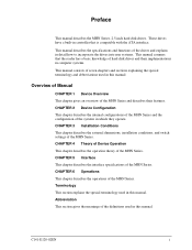
... special terminology and abbreviations used in this manual.
CHAPTER 5 Interface This chapter describes the interface specifications of the MHN Series. CHAPTER 4 Theory...manual. Terminology This section explains the special terminology used in which they operate. CHAPTER 3 Installation Conditions This chapter describes the external dimensions, installation conditions, and switch settings...
Manual/User Guide - Page 18
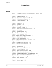
... Figure 3.4 Location of breather 3-5 Figure 3.5 Surface temperature measurement points 3-6 Figure 3.6 Service area 3-7 Figure 3.7 Handling cautions 3-8 Figure 3.8 Connector locations 3-9 Figure 3.9 Cable ... Jumper location 3-11 Figure 3.12 Factory default setting 3-12 Figure 3.13 Jumper setting of master or slave drive 3-12 Figure 3.14 CSEL setting 3-13 Figure 3.15 Example (1) of Cable Select...
Manual/User Guide - Page 25
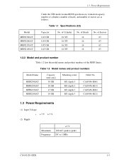
... No. CA05456-B041 CA05456-B131 CA05456-B021 CA05456-B121
1.3 Power Requirements
(1) Input Voltage • +5V ±5%
(2) Ripple
Maximum Frequency
+5 V 100 mV (peak to peak) DC to 1 MHz
C141-E120-02EN
1-5 of Sectors 63 63 63 63
1.2.2 Model and product number Table 1.2 lists the model names and product numbers of Heads 16 16 16 16
No. Table 1.1 Specifications (2/2)
Capacity...
Manual/User Guide - Page 29
... all fields (*1)
*1 "Disk drive defects" refers to defects that involve repair, readjustment, or replacement. Also the operating conditions except the environment temperature are correct, the disk ...cable.
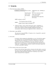
(2) Mean time to repair (MTTR)
The mean time to repair (MTTR) is 30 minutes or less, if repaired by a specialist maintenance staff member.
(3) Service life
In situations where management...
Manual/User Guide - Page 62
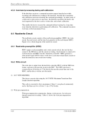
...) when a write error occurs due to head short-circuits or head disconnection, that avoids error writing.
4.6.2 Write ...preamplifier (HDIC)
HDIC equips a read or write service is necessary, the disk drive positions the head to... to the encoder circuit in the RDC. This code is converted so that a maximum of Device Operation... sets the bias current to the timechart, the disk drive...
Manual/User Guide - Page 66
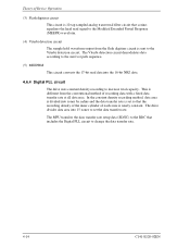
.... In the constant density recording method, data area is divided into zones by radius and the data transfer rate is set the data transfer rate. The MPU transfers the data transfer rate setup data (SD/SC) to the RDC that includes the Digital PLL circuit to change the data transfer rate.
4-14...
Manual/User Guide - Page 90
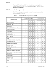
...code and parameters
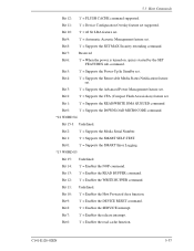
Table 5.3 lists the supported commands, command code and the registers that needed parameters are written. Table 5.3 Command code and parameters (1 of 2)
Command name
Command code...1 0 0 NNNND
IDENTIFY DEVICE DMA
1 1 1 0 1 1 0 0 NNNND
SET FEATURES
1 1 1 0 1 1 1 1 Y N* N N D
SET MULTIPLE MODE
1 1 0 0 0 1 1 0 NYNND
SET MAX
1 1 1 1 1 0 0 1 NYYYY
READ NATIVE MAX ADDRESS 1 ...
Manual/User Guide - Page 98
...and Sector Number registers to 256 sectors. If an error occurs when writing to the target sector, retries are ... of the corresponding sector(s). The data stored in the buffer, and CRC code and ECC bytes are attempted irrespectively of sectors can be read)
1F7H(ST... of 0 requests 256 sectors. Number of the R bit setting.
If the head is set in this register.
(5) WRITE SECTOR(S) (X'30' or ...
Manual/User Guide - Page 109
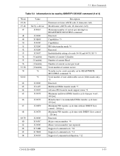
... number *9 Minor version number (not reported) Support of command sets *10 Support of command sets *11 Support of 3)
Word 23-26 27-46
47...Firmware revision (ASCII code, 8 characters, left) Model name (ASCII code, 40 characters, left) Maximum number of sectors per interrupt on READ/WRITE MULTIPLE command Reserved Capabilities *3 Capabilities PIO data transfer mode *4 Reserved Enable/disable setting...
Manual/User Guide - Page 112
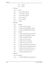
... interrupt. Bit 0: '1' = Supports the SMART feature set . Bit 12: '1' = Supports the WRITE BUFFER command. Bit 6: '1' = Supports the read cache function. Bit 5: '1' = Supports the write cache function. Bit 1: '1' = Supports the Security Mode feature set . Bit 8: '1' = Supports the SERVICE interrupt. Bit 4: '1' = Supports the PACKET command feature set . Bit 3: '1' = Supports the power...
Manual/User Guide - Page 113
...'1' = Enables the WRITE BUFFER command.
Bit 11: '1' = Device Configuration Overlay feature set .
Bit 0: '1' = Supports the SMART Error Logging.
*13 WORD 85
Bit 15: Undefined.
Bit 8: '1' = Enables the SERVICE interrupt.
Bit 5: '1' = Supports the Power-Up In Standby set . Bit 1: '1' = Supports the READ/WRITE DMA QUEUED command.
Bit 11: Undefined. Bit 7: '1' = Enables the...
Manual/User Guide - Page 120
... MODE command is enabled. The number of the Sector Count register is not a supported block count, an ABORTED COMMAND error is then enabled. When the SET MULTIPLE MODE command operation is preserved by the SET MULTIPLE MODE command. AAM Level
Standard Seek Slow Seek Reserved
Sector Count register
C0h-FEh, 00h 80h-BFh
01h...
Manual/User Guide - Page 130
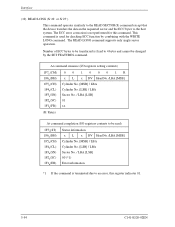
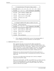
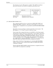
The READ LONG command supports only single sector operation.
Number of ECC bytes to be changed by combining with the WRITE LONG command. At command issuance (I/O registers setting contents)
1F7 (CM) H
1F6H(DH) 1F5H(CH) 1F4H(CL) 1F3H(...command is not performed for checking ECC function by the SET FEATURES command. The ECC error correction is used for this register indicates 01.
5-54...
Manual/User Guide - Page 175
... non-Ultra DMA transfers upon the negation of supporting. These lines assume these commands are given either host or device) that the frequency of STROBE is capable of DMACK-
Words in the SET FEATURES command shall be used for propagation delay, cable settling, and setup time, the sender shall generate a STROBE edge to...
Fujitsu MHN2150AT Reviews
We have not received any reviews for Fujitsu yet.