Wiring Diagram (All Languages)
Page 1
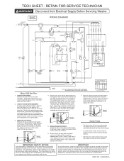
...the speed control unit. DASHED LINES INDICATE CIRCUITS NOT ON ALL MODELS. WATER TEMP SWITCH SWITCH POSITION CIRCUIT W/R 1 - 3 1 - 5 2 - 4 H/C X W/C XX C/C X * W/W XXX X= CONTACTS CLOSED * NOT ON ALL MODELS 4. Remove the ten pin plug from the washer and remove the back panel. The voltage at pins 2, 6, ...adequate background of the 6 pin plug on the speed control board. Remove the 6 pin plug from Electrical Supply Before Servicing Washer. Remove electrical power from the speed control unit. Timer/off to pin 5 of electrical, electronic and mechanical experience. Reconnect ...
...the speed control unit. DASHED LINES INDICATE CIRCUITS NOT ON ALL MODELS. WATER TEMP SWITCH SWITCH POSITION CIRCUIT W/R 1 - 3 1 - 5 2 - 4 H/C X W/C XX C/C X * W/W XXX X= CONTACTS CLOSED * NOT ON ALL MODELS 4. Remove the ten pin plug from the washer and remove the back panel. The voltage at pins 2, 6, ...adequate background of the 6 pin plug on the speed control board. Remove the 6 pin plug from Electrical Supply Before Servicing Washer. Remove electrical power from the speed control unit. Timer/off to pin 5 of electrical, electronic and mechanical experience. Reconnect ...
Wiring Diagram (All Languages)
Page 2
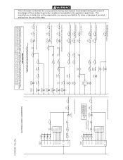
... responsible, nor assume any liability, for service, they must be returned to their original position and properly fastened. DASHED LINES INDICATE CIRCUITS NOT ON ALL MODELS. MOTOR 12T TIMER 14C TIMER * TIMER CONTACTS SHOWN AT THE START OF THE REGULAR WASH CYCLE. * 1C * 3C * 5C * 7C 1B TIMER 3B TIMER 5B...
... responsible, nor assume any liability, for service, they must be returned to their original position and properly fastened. DASHED LINES INDICATE CIRCUITS NOT ON ALL MODELS. MOTOR 12T TIMER 14C TIMER * TIMER CONTACTS SHOWN AT THE START OF THE REGULAR WASH CYCLE. * 1C * 3C * 5C * 7C 1B TIMER 3B TIMER 5B...
Wiring Diagram (All Languages)
Page 5
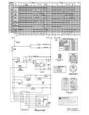
...C10.3(T2) 0 3 2 MOTOR 5 TACHO GENERATOR MOTOR 4 FAME SPEED CONTROL UNIT NOTE DASHED UNES INDICATE CIRCUITS THAT ARE NOT IN ALL MODELS. B SIGNAL L DINA RINSE SNITCH BUZZER SNITCH 8 MIER MOTOR 3.103.3 WAX MOTOR 1C) PUMP MOTOR -• 131 Ct8i .8 o ...;7% ID O MOTOR PLUG-MALE (END NEW) WIRING CODES 4- WIRING DIAGRAM P/N 134968300 A N)- 5 TEMP SWITCH • WATER VALVE FIOT • JIB 14 11 °"..1 12 CYCLE? "0. NO LOAD, START POSITION OF PERMANENT PRESS WHITE SIDE 1 I 11231241 3 I I PI I 5 I H 1118 1 7 N I 1115 1 9 I e ll I 11 I Fi l l 13 15 TC B D BLACK ...
...C10.3(T2) 0 3 2 MOTOR 5 TACHO GENERATOR MOTOR 4 FAME SPEED CONTROL UNIT NOTE DASHED UNES INDICATE CIRCUITS THAT ARE NOT IN ALL MODELS. B SIGNAL L DINA RINSE SNITCH BUZZER SNITCH 8 MIER MOTOR 3.103.3 WAX MOTOR 1C) PUMP MOTOR -• 131 Ct8i .8 o ...;7% ID O MOTOR PLUG-MALE (END NEW) WIRING CODES 4- WIRING DIAGRAM P/N 134968300 A N)- 5 TEMP SWITCH • WATER VALVE FIOT • JIB 14 11 °"..1 12 CYCLE? "0. NO LOAD, START POSITION OF PERMANENT PRESS WHITE SIDE 1 I 11231241 3 I I PI I 5 I H 1118 1 7 N I 1115 1 9 I e ll I 11 I Fi l l 13 15 TC B D BLACK ...
Installation Instructions (All Languages)
Page 2
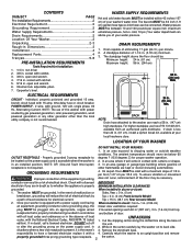
...single phase, 60 Hz, Alternating Current. ELECTRICAL REQUIREMENTS CIRCUIT - POWER SUPPLY - 2 wire, with ratchet. 5. 9/16 in . (0 cm) Front Console Model a path of eliminating 17 gals (64.3 L) per 30.5 cm). WATER SUPPLY REQUIREMENTS Hot and cold water faucets MUST be below 60 OUTLET ... dripping water or outside weather conditions. per foot (1.27 cm per minute. 2. Since your washer's water inlet. cold, 10 psi.) Your water department can be necessary. other than 24 in . When installed in . (38.1 cm) Rear Console Model 2. Channel-lock adjustable pliers. 7. NOTE: Drain hose ...
...single phase, 60 Hz, Alternating Current. ELECTRICAL REQUIREMENTS CIRCUIT - POWER SUPPLY - 2 wire, with ratchet. 5. 9/16 in . (0 cm) Front Console Model a path of eliminating 17 gals (64.3 L) per 30.5 cm). WATER SUPPLY REQUIREMENTS Hot and cold water faucets MUST be below 60 OUTLET ... dripping water or outside weather conditions. per foot (1.27 cm per minute. 2. Since your washer's water inlet. cold, 10 psi.) Your water department can be necessary. other than 24 in . When installed in . (38.1 cm) Rear Console Model 2. Channel-lock adjustable pliers. 7. NOTE: Drain hose ...


