Wiring Diagram (All Languages)
Page 1
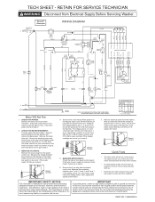
... #1 WHT #3 WHT #7 WHT NOTE: BOLD LINES INDICATE INTERNAL TIMER JUMPER WIRES. Remove the 6 pin plug from Electrical Supply Before Servicing Washer. Measure the resistance between pins 1 and 2, 2 and 3, and 3 and 1 of the 6 pin plug on the speed control board. Any attempt to step 2. 2. TECH SHEET - RETAIN FOR SERVICE TECHNICIAN Disconnect from the speed...
... #1 WHT #3 WHT #7 WHT NOTE: BOLD LINES INDICATE INTERNAL TIMER JUMPER WIRES. Remove the 6 pin plug from Electrical Supply Before Servicing Washer. Measure the resistance between pins 1 and 2, 2 and 3, and 3 and 1 of the 6 pin plug on the speed control board. Any attempt to step 2. 2. TECH SHEET - RETAIN FOR SERVICE TECHNICIAN Disconnect from the speed...
Wiring Diagram (All Languages)
Page 2
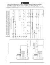
... This information is energized: pump, drive motor and electronic control boards. L1 DOOR LAMP WON'T LIGHT OR DOOR LOCK SOLENOID ...TIMER 5B TIMER 7B TIMER C10.4 (T1) C6.4 (GND) C10.2 (A) C10.1 (B) C10.6 (C) C10.10 (D) SPEED CONTROL IF WATER PUMP DOES NOT WORK 0T 0C TIMER 2.2 4.3 DOOR LOCK IF WATER PUMP DOES NOT WORK IN EXTRA RINSE 0T ...C6.3 (P3) C10.3 (T2) C10.4 (T1) C6.4 (GND) C10.2 (A) C10.1 (B) C10.6 (C) C10.10 (D) SPEED CONTROL NOTE: BOLD LINES INDICATE INTERNAL TIMER JUMPER WIRES. DIAGNOSTIC STRIP CIRCUITS PART NO. 134968300 A DASHED LINES INDICATE CIRCUITS NOT ON ALL MODELS....
... This information is energized: pump, drive motor and electronic control boards. L1 DOOR LAMP WON'T LIGHT OR DOOR LOCK SOLENOID ...TIMER 5B TIMER 7B TIMER C10.4 (T1) C6.4 (GND) C10.2 (A) C10.1 (B) C10.6 (C) C10.10 (D) SPEED CONTROL IF WATER PUMP DOES NOT WORK 0T 0C TIMER 2.2 4.3 DOOR LOCK IF WATER PUMP DOES NOT WORK IN EXTRA RINSE 0T ...C6.3 (P3) C10.3 (T2) C10.4 (T1) C6.4 (GND) C10.2 (A) C10.1 (B) C10.6 (C) C10.10 (D) SPEED CONTROL NOTE: BOLD LINES INDICATE INTERNAL TIMER JUMPER WIRES. DIAGNOSTIC STRIP CIRCUITS PART NO. 134968300 A DASHED LINES INDICATE CIRCUITS NOT ON ALL MODELS....


