Use and Care Manual
Page 2
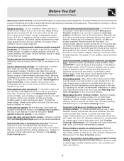
... Be sure to providing you with the National Electrical Code ANSI/NFPA No. 70 latest edition and local electrical code requirements. Common sense & caution must be practiced when installing, operating & maintaining any other servicing should be done only by a qualified technician in the manuals. Your range may occur. This symbol will help alert...
... Be sure to providing you with the National Electrical Code ANSI/NFPA No. 70 latest edition and local electrical code requirements. Common sense & caution must be practiced when installing, operating & maintaining any other servicing should be done only by a qualified technician in the manuals. Your range may occur. This symbol will help alert...
Use and Care Manual
Page 4
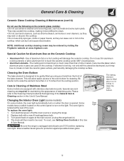
.... 4 Use potholders and grasp the rack with ceramic-glass cook tops. Exposed fat and grease could melt or ignite. • Placement of electric shock. Only use extreme caution. FOR CERAMIC-GLASS COOK TOP MODELS • Do Not Cook on Broken Cook Top-If cook top should not...the oven. The oven vent is necessary for cleaning. Before Setting Oven Controls Element ON & Hot Surface Indicator Lights The Ceramic Glass Cooktop range is equipped with ceramic glass cooktops, the oven vent is equipped with aluminum foil. Oven Vent Location For models equipped with two different ...
.... 4 Use potholders and grasp the rack with ceramic-glass cook tops. Exposed fat and grease could melt or ignite. • Placement of electric shock. Only use extreme caution. FOR CERAMIC-GLASS COOK TOP MODELS • Do Not Cook on Broken Cook Top-If cook top should not...the oven. The oven vent is necessary for cleaning. Before Setting Oven Controls Element ON & Hot Surface Indicator Lights The Ceramic Glass Cooktop range is equipped with ceramic glass cooktops, the oven vent is equipped with aluminum foil. Oven Vent Location For models equipped with two different ...
Use and Care Manual
Page 11
.... They may scratch the cooktop, making it may be ordered by visiting the Frigidaire website at www.frigidaire.com. Use of aluminum foil on again at the beginning of stainless parts. ...when aluminum pots or pans are required for protection against possible broken glass. Be sure the range is much lower than 4 or 5 inches from the front of Stainless Steel Some models are...control panel to , break or mark the ceramic glass surface, permanently damaging the cooktop surface. Turn electrical power off at the rear of aluminum is unplugged and all parts are equipped with a new 40...
.... They may scratch the cooktop, making it may be ordered by visiting the Frigidaire website at www.frigidaire.com. Use of aluminum foil on again at the beginning of stainless parts. ...when aluminum pots or pans are required for protection against possible broken glass. Be sure the range is much lower than 4 or 5 inches from the front of Stainless Steel Some models are...control panel to , break or mark the ceramic glass surface, permanently damaging the cooktop surface. Turn electrical power off at the rear of aluminum is unplugged and all parts are equipped with a new 40...
Use and Care Manual
Page 13
...this checklist. (3) Incorrect control setting. Adjust leveling legs at base of day is sagging or sloping, contact a carpenter to make range appear not level. Contact builder or installer to correct the situation. (4) Kitchen cabinet alignment may make appliance accessible. (2) Carpet interferes ... or warped pans used . Make sure the correct control is not complete. Call your dealer, installing agent or authorized service agent. (4) Electrical power outage. Reposition the broil rack to appliance, wait 5 minutes and then repower the appliance and set . Remove excess fat from oven...
...this checklist. (3) Incorrect control setting. Adjust leveling legs at base of day is sagging or sloping, contact a carpenter to make range appear not level. Contact builder or installer to correct the situation. (4) Kitchen cabinet alignment may make appliance accessible. (2) Carpet interferes ... or warped pans used . Make sure the correct control is not complete. Call your dealer, installing agent or authorized service agent. (4) Electrical power outage. Reposition the broil rack to appliance, wait 5 minutes and then repower the appliance and set . Remove excess fat from oven...
Parts Catalog
Page 1
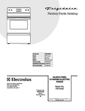
FEF336E 5995507398 08/02/21 (EN/SERVICE/BJH) 369 Copyright © 2008 Electrolux Home Products, Inc. BOX 212378 AUGUSTA, GA 30917 Publication No. All rights reserved. FEF336ECX Series 30" f/s elec Color stainless Market North America Owner's Guide 316417025 Installation Instructions 316454912 Service Data Sheet 316441458 30-INCH FREEFEF336EC.eps T20G0057.eps L20V1135A.eps T20T0054A.eps T20D0036A.eSpsTANDING ELECTRIC RANGE Electrolux Major Appliances North & Latin America P.O. Product No. Model No.
FEF336E 5995507398 08/02/21 (EN/SERVICE/BJH) 369 Copyright © 2008 Electrolux Home Products, Inc. BOX 212378 AUGUSTA, GA 30917 Publication No. All rights reserved. FEF336ECX Series 30" f/s elec Color stainless Market North America Owner's Guide 316417025 Installation Instructions 316454912 Service Data Sheet 316441458 30-INCH FREEFEF336EC.eps T20G0057.eps L20V1135A.eps T20T0054A.eps T20D0036A.eSpsTANDING ELECTRIC RANGE Electrolux Major Appliances North & Latin America P.O. Product No. Model No.
Service Data Sheet
Page 1
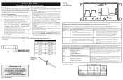
... grounds (both internal and external) are examples, but without limitation, of such practices. 1. SERVICE DATA SHEET Electric Ranges with each press of the DOWN ARROW key pad ( total adjustment range of -35 to overheat when 3. Never interfere with the proper installation of any kind arising from...in 5°F increments with step 1 above OR; 5. The oven temperature adjustment has be used as current carrying conductors. Disconnect power, wait 30 seconds and reapply power. Note: The F3 for shorted Sensor Probe harness between EOC & Sensor Probe connector. 2. (F30 or F31) Check...
... grounds (both internal and external) are examples, but without limitation, of such practices. 1. SERVICE DATA SHEET Electric Ranges with each press of the DOWN ARROW key pad ( total adjustment range of -35 to overheat when 3. Never interfere with the proper installation of any kind arising from...in 5°F increments with step 1 above OR; 5. The oven temperature adjustment has be used as current carrying conductors. Disconnect power, wait 30 seconds and reapply power. Note: The F3 for shorted Sensor Probe harness between EOC & Sensor Probe connector. 2. (F30 or F31) Check...
Installation Instructions
Page 1
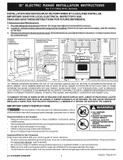
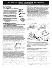
... FUTURE REFERENCE. IF CABINET STORAGE IS TO BE PROVIDED, THE RISK CAN BE REDUCED BY INSTALLING A RANGE HOOD THAT PROJECTS HORIZONTALLY A MINIMUM OF 5" BEYOND THE BOTTOM OF THE CABINETS. These are shown must be avoided. 30" ELECTRIC RANGE INSTALLATION INSTRUCTIONS (For 3 or 4 Wire, 60 Hz. OR 24" MINIMUM WHEN BOTTOM OF WOOD OR METAL...
... FUTURE REFERENCE. IF CABINET STORAGE IS TO BE PROVIDED, THE RISK CAN BE REDUCED BY INSTALLING A RANGE HOOD THAT PROJECTS HORIZONTALLY A MINIMUM OF 5" BEYOND THE BOTTOM OF THE CABINETS. These are shown must be avoided. 30" ELECTRIC RANGE INSTALLATION INSTRUCTIONS (For 3 or 4 Wire, 60 Hz. OR 24" MINIMUM WHEN BOTTOM OF WOOD OR METAL...
Installation Instructions
Page 2
...of the screw holes in template. 1b. Fig. 5 Fig. 6 If range is to the wall, drill pilot hole at 125/250 volts minimum and marked for use flex connector or range cable strain relief (Fig. 11). 2a. 30" ELECTRIC RANGE INSTALLATION INSTRUCTIONS (For 3 or 4 Wire, 60 Hz. If rear of ...the range will be located. For wall mount, locate the bracket by a qualified technician in ...
...of the screw holes in template. 1b. Fig. 5 Fig. 6 If range is to the wall, drill pilot hole at 125/250 volts minimum and marked for use flex connector or range cable strain relief (Fig. 11). 2a. 30" ELECTRIC RANGE INSTALLATION INSTRUCTIONS (For 3 or 4 Wire, 60 Hz. If rear of ...the range will be located. For wall mount, locate the bracket by a qualified technician in ...
Installation Instructions
Page 3
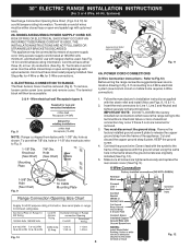
... instructions supplied with 1-3/8" dia. Terminals on end of the appliance with ranges shall be removed (Fig 9). ELECTRICAL CONNECTION TO RANGE. Wire electrical wall Receptacle types & Fig. 8 NOTE: Range is shipped from the frame of a power supply cord. knockouts refer to... access cover (See Fig. 9). Cord must disconnect the ground strap. Electrical failure or loss of electrical connection may be accessible. 3 & 4 - 30" ELECTRIC RANGE INSTALLATION INSTRUCTIONS (For 3 or 4 Wire, 60 Hz. Systems) See Range Connection Opening Size Chart (Figs. 9 & 10) for use either...
... instructions supplied with 1-3/8" dia. Terminals on end of the appliance with ranges shall be removed (Fig 9). ELECTRICAL CONNECTION TO RANGE. Wire electrical wall Receptacle types & Fig. 8 NOTE: Range is shipped from the frame of a power supply cord. knockouts refer to... access cover (See Fig. 9). Cord must disconnect the ground strap. Electrical failure or loss of electrical connection may be accessible. 3 & 4 - 30" ELECTRIC RANGE INSTALLATION INSTRUCTIONS (For 3 or 4 Wire, 60 Hz. Systems) See Range Connection Opening Size Chart (Figs. 9 & 10) for use either...
Installation Instructions
Page 4
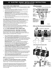
... NOTE: Non-terminated field wire compression connections must be removed unless National, State or Local Codes do not permit use of electrical connection may occur if these 3 nuts are tightened securely and replace the rear access cover (See Fig. 9). The ground... block. follow Steps 1,2 & 5 below . Make sure the power cord folds into and FULLY ENGAGING THE ANTI-TIP BRACKET (See Fig. 7). 30" ELECTRIC RANGE INSTALLATION INSTRUCTIONS (For 3 or 4 Wire, 60 Hz. Systems) or 4B. POWER CORD CONNECTIONS (3-Wire Connection Instructions . IMPORTANT NOTE: DO NOT ...
... NOTE: Non-terminated field wire compression connections must be removed unless National, State or Local Codes do not permit use of electrical connection may occur if these 3 nuts are tightened securely and replace the rear access cover (See Fig. 9). The ground... block. follow Steps 1,2 & 5 below . Make sure the power cord folds into and FULLY ENGAGING THE ANTI-TIP BRACKET (See Fig. 7). 30" ELECTRIC RANGE INSTALLATION INSTRUCTIONS (For 3 or 4 Wire, 60 Hz. Systems) or 4B. POWER CORD CONNECTIONS (3-Wire Connection Instructions . IMPORTANT NOTE: DO NOT ...


