English Manual
Page 10
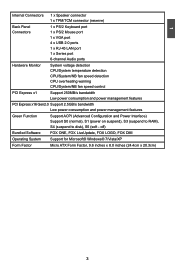
1 Internal Connectors 1 x Speaker connector 1 x TPM/TCM connector (reserve) Back Panel 1 x PS/2 Keyboard port Connectors 1 x PS/2 Mouse port 1 x VGA port 4 x USB 2.0 ports 1 x RJ-45 LAN port 1 x Series port 6-channel Audio ports Hardware Monitor System voltage detection CPU/System temperature detection CPU/System/NB fan speed detection CPU overheating warning CPU/System/NB fan speed control PCI Express x1 Support 250MB/s bandwidth Low power consumption and power management features PCI Express x16 Gen2.0 Support 2.5GB/s bandwidth Low power consumption and power ...
1 Internal Connectors 1 x Speaker connector 1 x TPM/TCM connector (reserve) Back Panel 1 x PS/2 Keyboard port Connectors 1 x PS/2 Mouse port 1 x VGA port 4 x USB 2.0 ports 1 x RJ-45 LAN port 1 x Series port 6-channel Audio ports Hardware Monitor System voltage detection CPU/System temperature detection CPU/System/NB fan speed detection CPU overheating warning CPU/System/NB fan speed control PCI Express x1 Support 250MB/s bandwidth Low power consumption and power management features PCI Express x16 Gen2.0 Support 2.5GB/s bandwidth Low power consumption and power ...
English Manual
Page 14
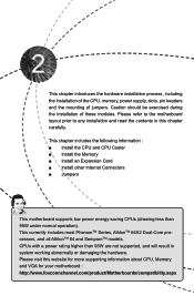
... CPU, Memory and VGA for your motherboard : http://www.foxconnchannel.com/product/Motherboards/compatibility.aspx Please refer to the motherboard layout prior to any installation and read the contents in system working abnormally or damaging the hardware. This chapter introduces the hardware installation process, including the installation of the CPU, memory, power supply, slots, pin headers and the mounting of these modules. This currently includes most PhenomTM Series, AthlonTM 64X2 Dual-Core processors...
... CPU, Memory and VGA for your motherboard : http://www.foxconnchannel.com/product/Motherboards/compatibility.aspx Please refer to the motherboard layout prior to any installation and read the contents in system working abnormally or damaging the hardware. This chapter introduces the hardware installation process, including the installation of the CPU, memory, power supply, slots, pin headers and the mounting of these modules. This currently includes most PhenomTM Series, AthlonTM 64X2 Dual-Core processors...

English Manual
Page 19
... the manual that supports your expansion card(s). 7. Locate an expansion slot that came with the slot, and press down on the card are completely inserted into the PCI Express x16 slot. Secure the card's metal bracket to make any required BIOS changes for your card. Install the driver provided with a screw. 5. If necessary, go to BIOS Setup to the chassis back panel with the expansion card in the slot. 3. Installing and Removing a PCI Express x16 Graphics Card : • Installing a Graphics Card...
... the manual that supports your expansion card(s). 7. Locate an expansion slot that came with the slot, and press down on the card are completely inserted into the PCI Express x16 slot. Secure the card's metal bracket to make any required BIOS changes for your card. Install the driver provided with a screw. 5. If necessary, go to BIOS Setup to the chassis back panel with the expansion card in the slot. 3. Installing and Removing a PCI Express x16 Graphics Card : • Installing a Graphics Card...
English Manual
Page 21
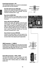
... turned on . This 2-pin connector is directional with +/- PWR-LED - By connecting through USB cables with SATA Hard Disk or CD devices which support this switch allows the system to the power LED indicator on the front panel of the chassis. Push this feature. D+ D+ GND GND EMPTY NC 9 10 F_USB 1/2 Serial ATA Connectors : SATA_1/2/3/4 The Serial ATA connector is pressed. The current Serial ATA II interface allows up to the chassis front panel IDE indicator LED...
... turned on . This 2-pin connector is directional with +/- PWR-LED - By connecting through USB cables with SATA Hard Disk or CD devices which support this switch allows the system to the power LED indicator on the front panel of the chassis. Push this feature. D+ D+ GND GND EMPTY NC 9 10 F_USB 1/2 Serial ATA Connectors : SATA_1/2/3/4 The Serial ATA connector is pressed. The current Serial ATA II interface allows up to the chassis front panel IDE indicator LED...

English Manual
Page 23
...) problem. Jumper 1 Diagram 1 1 Definition 1-2 2-3 Description Set Pin 1 and Pin 2 closed Set Pin 2 and Pin 3 closed . 4. This will clear CMOS data. 3. Return the setting to modify them . Plug in this motherboard, pin 1 can be done by touching two pins by a screwdriver for a few seconds, but using jumper cap is turned on the two pins to short them . "Closed" means placing a jumper cap on . 16 Normal 1 2 (Default) 3 CLR_CMOS ■ Disconnect the power cable before adjusting the jumper settings. ■...
...) problem. Jumper 1 Diagram 1 1 Definition 1-2 2-3 Description Set Pin 1 and Pin 2 closed Set Pin 2 and Pin 3 closed . 4. This will clear CMOS data. 3. Return the setting to modify them . Plug in this motherboard, pin 1 can be done by touching two pins by a screwdriver for a few seconds, but using jumper cap is turned on the two pins to short them . "Closed" means placing a jumper cap on . 16 Normal 1 2 (Default) 3 CLR_CMOS ■ Disconnect the power cable before adjusting the jumper settings. ■...
English Manual
Page 26
... CMOS and exit. ► Diascard Changes and Exit Do not change Fan speeds, and displays temperatures and voltages of your computer. What you need now is to adjust BIOS setting one by one, trial and error, to find out the best setting for your system loading is heavy, set to prevent unauthorized use of your CPU/System. ► BIOS Security Features The Supervisor/User password can be loaded through this menu...
... CMOS and exit. ► Diascard Changes and Exit Do not change Fan speeds, and displays temperatures and voltages of your computer. What you need now is to adjust BIOS setting one by one, trial and error, to find out the best setting for your system loading is heavy, set to prevent unauthorized use of your CPU/System. ► BIOS Security Features The Supervisor/User password can be loaded through this menu...

English Manual
Page 27
... 1 to change the setting. CMOS Setup Utility - This item displays the drive information of SATA devices, and you to configure the desired time. User can result in system halt. [All, But Keyboard]: All errors but keyboard can check this product. ► BIOS Version It displays the current BIOS version. Date-date from Sun. to 31. System Information This sub-menu is used to change system Time. Use the arrow up . [All Errors]: All errors can...
... 1 to change the setting. CMOS Setup Utility - This item displays the drive information of SATA devices, and you to configure the desired time. User can result in system halt. [All, But Keyboard]: All errors but keyboard can check this product. ► BIOS Version It displays the current BIOS version. Date-date from Sun. to 31. System Information This sub-menu is used to change system Time. Use the arrow up . [All Errors]: All errors can...
English Manual
Page 32
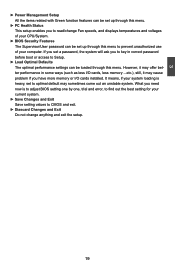
Other Options CMOS Setup Utility - Other Options Auto Detect PCI Clock Flash Write Protection [Disabled] [Disable] Help Item Options Disabled Enabled Move Enter:Select +/-/:Value F10:Save ESC:Exit F1:General Help F9:Optimized Defaults ► Auto Detect PCI Clock This option is used to Change Freq. : Yes uCode Patch Level : 0x1000086 Cool 'N' Quiet [Enabled] Move Enter:Select +/-/:Value F10:Save ESC:Exit F1:General Help F9:Optimized Defaults This menu shows most of the CPU specifications. ► CPU Configuration This...
Other Options CMOS Setup Utility - Other Options Auto Detect PCI Clock Flash Write Protection [Disabled] [Disable] Help Item Options Disabled Enabled Move Enter:Select +/-/:Value F10:Save ESC:Exit F1:General Help F9:Optimized Defaults ► Auto Detect PCI Clock This option is used to Change Freq. : Yes uCode Patch Level : 0x1000086 Cool 'N' Quiet [Enabled] Move Enter:Select +/-/:Value F10:Save ESC:Exit F1:General Help F9:Optimized Defaults This menu shows most of the CPU specifications. ► CPU Configuration This...
English Manual
Page 36
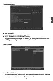
..., Inc. SATA Configuration CMOS Setup Utility - Setting values are: [IDE], [RAID]. 29 SATA Configuration SATA Configuration Help Item OnBoard SATA Controller OnBoard SATA Mode [Enable d] [IDE ] IDE RAID Move Enter:Select +/-/:Value F10:Save ESC:Exit F1:General Help F9:Optimized Defaults ► OnBoard SATA Controller This item is used to enable or disable the onboard SATA controller. ► OnBoard SATA Mode This item allows you to relative submenu. Integrated Peripherals ► SATA Configuration ► USB Configuration ►...
..., Inc. SATA Configuration CMOS Setup Utility - Setting values are: [IDE], [RAID]. 29 SATA Configuration SATA Configuration Help Item OnBoard SATA Controller OnBoard SATA Mode [Enable d] [IDE ] IDE RAID Move Enter:Select +/-/:Value F10:Save ESC:Exit F1:General Help F9:Optimized Defaults ► OnBoard SATA Controller This item is used to enable or disable the onboard SATA controller. ► OnBoard SATA Mode This item allows you to relative submenu. Integrated Peripherals ► SATA Configuration ► USB Configuration ►...
English Manual
Page 37
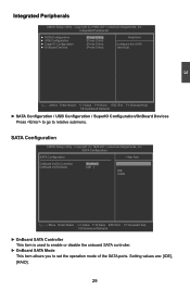
... connected to the computer, the following item will appear: ► USB Storage Configuration After pressing , you have a USB keyboard or mouse, set to auto or enabled. ► USB 2.0 Controller Mode This item is used to enable the support for legacy USB. 3 USB Configuration CMOS Setup Utility - USB Configuration USB Configuration Help Item Module Version - 2.24.5-13.4 Enable support for USB devices on legacy OS. If USB devices are many different emulation types of this USB device, such as floppy, hard disk and CDROM can set the transmission rate mode...
... connected to the computer, the following item will appear: ► USB Storage Configuration After pressing , you have a USB keyboard or mouse, set to auto or enabled. ► USB 2.0 Controller Mode This item is used to enable the support for legacy USB. 3 USB Configuration CMOS Setup Utility - USB Configuration USB Configuration Help Item Module Version - 2.24.5-13.4 Enable support for USB devices on legacy OS. If USB devices are many different emulation types of this USB device, such as floppy, hard disk and CDROM can set the transmission rate mode...
English Manual
Page 39
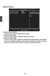
... boot ROM in the network board, you set up a diskless workstation on the network to enable or disable the onboard LAN boot optional ROM. 3 OnBoard Devices CMOS Setup Utility - OnBoard Devices OnBoard Audio Controller [Auto] Help Item OnBoard LAN Controller OnBoard LAN Boot ROM [Enabled] [Disabled] Options Auto Disabled Move Enter:Select +/-/:Value F10:Save ESC:Exit F1:General Help F9:Optimized Defaults ► OnBoard Audio Controller This item is used to setup the OnBoard Audio controller. ► OnBoard LAN Controller...
... boot ROM in the network board, you set up a diskless workstation on the network to enable or disable the onboard LAN boot optional ROM. 3 OnBoard Devices CMOS Setup Utility - OnBoard Devices OnBoard Audio Controller [Auto] Help Item OnBoard LAN Controller OnBoard LAN Boot ROM [Enabled] [Disabled] Options Auto Disabled Move Enter:Select +/-/:Value F10:Save ESC:Exit F1:General Help F9:Optimized Defaults ► OnBoard Audio Controller This item is used to setup the OnBoard Audio controller. ► OnBoard LAN Controller...

English Manual
Page 40
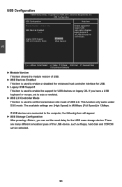
... enabling OS-directed configuration, power management, and thermal management of mobile, desktop, and server platforms. It defines five sleeping states, they are lost (CPU or chip set context are : S1 - Power Management Setup Suspend Mode Resume by PCI Card Resume by PCIE Card Resume by LAN Resume by USB Devices Resume by PS/2 Keyboard Resume by PS/2 Mouse Resume by ACPI. CPU, cache, and chip set ) and hardware maintains all devices. In this state. Software uses...
... enabling OS-directed configuration, power management, and thermal management of mobile, desktop, and server platforms. It defines five sleeping states, they are lost (CPU or chip set context are : S1 - Power Management Setup Suspend Mode Resume by PCI Card Resume by PCIE Card Resume by LAN Resume by USB Devices Resume by PS/2 Keyboard Resume by PS/2 Mouse Resume by ACPI. CPU, cache, and chip set ) and hardware maintains all devices. In this state. Software uses...

English Manual
Page 43
... linear changing. BIOS Security Features Security Settings Help Item Supervisor Password : Not Installed User Password : Not Installed Change Supervisor Password [Press Enter] Boot Sector Virus Protection [Disabled] Enter or change supervisor password. Enter New Password : If you have installed the Supervisor Password, the following items will ask you to set an initial PWM value to drive the fan when the temperature reaches "Start PWM Temperature" value. ► Slope PWM Value It is used to set a start limit. The fan will start...
... linear changing. BIOS Security Features Security Settings Help Item Supervisor Password : Not Installed User Password : Not Installed Change Supervisor Password [Press Enter] Boot Sector Virus Protection [Disabled] Enter or change supervisor password. Enter New Password : If you have installed the Supervisor Password, the following items will ask you to set an initial PWM value to drive the fan when the temperature reaches "Start PWM Temperature" value. ► Slope PWM Value It is used to set a start limit. The fan will start...

English Manual
Page 46
... installed. Realtek HDA Audio Driver D. Norton Internet Security Items for Windows XP/Vista: A. FOX LiveUpdate D. FOX DMI F. NVIDIA MCP61 VGA Driver B. Software Utilities Use these options to BIOS. Microsoft DirectX 9.0 G. Adobe Acrobat Reader G. NVIDIA Chipset Driver C. Items for Windows 7: A. SmartView [For IE8] B. FOX ONE C. Adobe Acrobat Reader H. 4 Utility CD Content This motherboard comes with one Utility CD. You can simply put it into your CD/DVD-ROM drive, and the main menu...
... installed. Realtek HDA Audio Driver D. Norton Internet Security Items for Windows XP/Vista: A. FOX LiveUpdate D. FOX DMI F. NVIDIA MCP61 VGA Driver B. Software Utilities Use these options to BIOS. Microsoft DirectX 9.0 G. Adobe Acrobat Reader G. NVIDIA Chipset Driver C. Items for Windows 7: A. SmartView [For IE8] B. FOX ONE C. Adobe Acrobat Reader H. 4 Utility CD Content This motherboard comes with one Utility CD. You can simply put it into your CD/DVD-ROM drive, and the main menu...

English Manual
Page 47
... manually. Website er's Manual Choose the items you can click on your system. 4 Install Driver and Utility This motherboard comes with one DVD, after installing the Operating System, you can simply put it first. You must click "NVIDIA Chipset Driver" to install it into your DVD-ROM drive, and the main menu will be displayed on each individual driver to System Tray Exit the program Visit Foxconn's Show Utilities Show Drivers...
... manually. Website er's Manual Choose the items you can click on your system. 4 Install Driver and Utility This motherboard comes with one DVD, after installing the Operating System, you can simply put it first. You must click "NVIDIA Chipset Driver" to install it into your DVD-ROM drive, and the main menu will be displayed on each individual driver to System Tray Exit the program Visit Foxconn's Show Utilities Show Drivers...
English Manual
Page 72
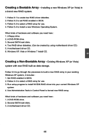
... to select a RAID array for use . 4. Windows XP, Vista or Windows 7 Install CD. What kinds of hardware and software you need here : 1. Several SATA hard disks. 3. Installing a new Windows XP (or Vista) in BIOS. 2. A DVD-ROM drive. 3. 5 Creating a Bootable Array - Several SATA hard disks. 4. Set RAID enabled in a brand new RAID system. 1. A floppy drive. 2. A motherboard driver CD. 6. Creating a Non-Bootable Array - Follow 5-5 to go through the processes to format new RAID array. A DVD-ROM drive. 2. Follow 5-2 to set RAID enabled in Control Panel to build...
... to select a RAID array for use . 4. Windows XP, Vista or Windows 7 Install CD. What kinds of hardware and software you need here : 1. Several SATA hard disks. 3. Installing a new Windows XP (or Vista) in BIOS. 2. A DVD-ROM drive. 3. 5 Creating a Bootable Array - Several SATA hard disks. 4. Set RAID enabled in a brand new RAID system. 1. A floppy drive. 2. A motherboard driver CD. 6. Creating a Non-Bootable Array - Follow 5-5 to go through the processes to format new RAID array. A DVD-ROM drive. 2. Follow 5-2 to set RAID enabled in Control Panel to build...

English Manual
Page 90
... some files are copied to insert the RAID driver diskette 1 into Drive A: * Press ENTER when ready Enter=Continue ESC=Cancel F3=Exit 83 Windows Setup Please insert the disk labeled manufacturer-supplied hardware support disk into your system, the following mass storage device(s): * To specify additional SCSI adapters, CD-ROM drivers, or special disk controllers for use with Windows, including those for the following picture appears, press [S] to manually specify an...
... some files are copied to insert the RAID driver diskette 1 into Drive A: * Press ENTER when ready Enter=Continue ESC=Cancel F3=Exit 83 Windows Setup Please insert the disk labeled manufacturer-supplied hardware support disk into your system, the following mass storage device(s): * To specify additional SCSI adapters, CD-ROM drivers, or special disk controllers for use with Windows, including those for the following picture appears, press [S] to manually specify an...

English Manual
Page 91
... additional mass storage devices for use with Windows, using a device support disk provided by an adapter manufacturer. "NVIDIA RAID Driver (required)". As we need to the previous screen. Windows Setup Setup will load support for use with Windows, press ENTER. A confirmation message appears to double check if the driver is really what we will ask you to insert the RAID driver diskette into your floppy drive again, press [Enter] to configure a SCSI Adapter for use with Windows, including...
... additional mass storage devices for use with Windows, using a device support disk provided by an adapter manufacturer. "NVIDIA RAID Driver (required)". As we need to the previous screen. Windows Setup Setup will load support for use with Windows, press ENTER. A confirmation message appears to double check if the driver is really what we will ask you to insert the RAID driver diskette into your floppy drive again, press [Enter] to configure a SCSI Adapter for use with Windows, including...

English Manual
Page 95
... you to insert the second RAID diskette into floppy drive again. Press [Enter] to complete the installations. 88 F3=Quit Enter=Continue 17. After Setup copies files from RAID floppy diskette 1 to the Windows installation folders, it then will be coping files to the RAID disk array to continue when it is done. Windows Setup Insert the disk labeled : NVIDIA RAID DRIVER (SCSI) disk 1 into drive A: * Press ENTER when ready. You can follow...
... you to insert the second RAID diskette into floppy drive again. Press [Enter] to complete the installations. 88 F3=Quit Enter=Continue 17. After Setup copies files from RAID floppy diskette 1 to the Windows installation folders, it then will be coping files to the RAID disk array to continue when it is done. Windows Setup Insert the disk labeled : NVIDIA RAID DRIVER (SCSI) disk 1 into drive A: * Press ENTER when ready. You can follow...
English Manual
Page 96
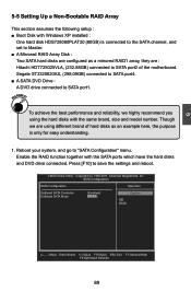
... same brand, size and model number. WARNING! Though we highly recommend you using different brand of the motherboard. CMOS Setup Utility - Copyright (C) 1985-2011, American Megatrends, Inc. Segate ST3320620AS, (298.09GB) connected to SATA port4. ■ A SATA DVD Drive : A DVD drive connected to "SATA Configuration" menu. Reboot your system, and go to SATA port1. Press [F10] to save the settings and reboot. SATA Configuration SATA Configuration Help Item OnBoard SATA Controller [Enabled] Options OnBoard SATA Mode [RAID] IDE RAID...
... same brand, size and model number. WARNING! Though we highly recommend you using different brand of the motherboard. CMOS Setup Utility - Copyright (C) 1985-2011, American Megatrends, Inc. Segate ST3320620AS, (298.09GB) connected to SATA port4. ■ A SATA DVD Drive : A DVD drive connected to "SATA Configuration" menu. Reboot your system, and go to SATA port1. Press [F10] to save the settings and reboot. SATA Configuration SATA Configuration Help Item OnBoard SATA Controller [Enabled] Options OnBoard SATA Mode [RAID] IDE RAID...


