
User manual
Page 1
D270S/D250S/D255/D255-S Motherboard User's Manual
D270S/D250S/D255/D255-S Motherboard User's Manual

User manual
Page 2
... disposal service or the shop where you want more detailed information about our products, please visit Foxconn's website: http://www.foxconnchannel.com © All rights reserved. Version: User's Manual V1.1 for D270S/D250S/D255/D255-S motherboard. WEEE: The use motherboard better, and tells you how to avoid problems. WARNING! All trade names are the property...
... disposal service or the shop where you want more detailed information about our products, please visit Foxconn's website: http://www.foxconnchannel.com © All rights reserved. Version: User's Manual V1.1 for D270S/D250S/D255/D255-S motherboard. WEEE: The use motherboard better, and tells you how to avoid problems. WARNING! All trade names are the property...

User manual
Page 3
declares that the product Motherboard D270S/D250S/D255/D255-S is in conformity with (reference to the specification under which conformity is declared in accordance with 89/336 EEC-EMC Directive) ■ EN 55022:1998/...
declares that the product Motherboard D270S/D250S/D255/D255-S is in conformity with (reference to the specification under which conformity is declared in accordance with 89/336 EEC-EMC Directive) ■ EN 55022:1998/...

User manual
Page 4
...: Type of conformity Trade Name: Model Name: Responsible Party: Address: Telephone: Facsimile: FOXCONN D270S/D250S/D255/D255-S PCE Industry Inc. 458 E. Operation is subject to comply with Part 15 of the FCC Rules. Declaration of Product: Manufacturer: Address: FCC Class B Subassembly Motherboard HON HAI PRECISION INDUSTRY COMPANY LTD 66 , CHUNG SHAN RD., TU-CHENG...
...: Type of conformity Trade Name: Model Name: Responsible Party: Address: Telephone: Facsimile: FOXCONN D270S/D250S/D255/D255-S PCE Industry Inc. 458 E. Operation is subject to comply with Part 15 of the FCC Rules. Declaration of Product: Manufacturer: Address: FCC Class B Subassembly Motherboard HON HAI PRECISION INDUSTRY COMPANY LTD 66 , CHUNG SHAN RD., TU-CHENG...

User manual
Page 5
...) wrist strap when handling components such as a spark which will quickly damage your electronic equipment. Incorrect connections might damage the motherboard. ■ When handling the motherboard, avoid touching any metal leads or connectors. ■ If there is any installation steps or have a problem related to ... voltage setting has been configured to the local standard. ■ To prevent damage to the motherboard, do not allow screws to the internal connectors on the motherboard, make sure there are no leftover screws or metal components placed on the overclocking capacity of the...
...) wrist strap when handling components such as a spark which will quickly damage your electronic equipment. Incorrect connections might damage the motherboard. ■ When handling the motherboard, avoid touching any metal leads or connectors. ■ If there is any installation steps or have a problem related to ... voltage setting has been configured to the local standard. ■ To prevent damage to the motherboard, do not allow screws to the internal connectors on the motherboard, make sure there are no leftover screws or metal components placed on the overclocking capacity of the...

User manual
Page 8
This chapter includes the following information: ■ Product Specifications ■ Layout ■ Back Panel Connectors Foxconn products are engineered to maximize computing power, providing only what you to unleash more power from your computer. D270S/D250S/D255/D255-S enables you need for buying Foxconn D270S/D250S/D255/D255-S motherboard. Thank you for break-through performance.
This chapter includes the following information: ■ Product Specifications ■ Layout ■ Back Panel Connectors Foxconn products are engineered to maximize computing power, providing only what you to unleash more power from your computer. D270S/D250S/D255/D255-S enables you need for buying Foxconn D270S/D250S/D255/D255-S motherboard. Thank you for break-through performance.

User manual
Page 11
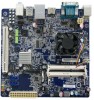
Front USB Connectors 4. Clear CMOS Jumper 7. IR/CIR Connector 13. Chipset: Intel® NM10 Express Note : The above motherboard layout is for reference only, please refer to the physical motherboard for detail. 4 SATA Connectors 9. Speaker Connector 6. TPM Connector 12. Front Panel Connector 10. 24-pin ATX Power Connector 11. System Fan Header 15. Front Audio Connector 3. PCI Slot 5. Chassis Intrusion Alarm Header 8. CPU Fan Header 16. 1 1-2 Layout 43 2 1 16 5 15 6 14 7 13 8 9 10 11 12 1. 4-pin ATX 12V Power Connector 2. DDR3 DIMM Slots 14.
Front USB Connectors 4. Clear CMOS Jumper 7. IR/CIR Connector 13. Chipset: Intel® NM10 Express Note : The above motherboard layout is for reference only, please refer to the physical motherboard for detail. 4 SATA Connectors 9. Speaker Connector 6. TPM Connector 12. Front Panel Connector 10. 24-pin ATX Power Connector 11. System Fan Header 15. Front Audio Connector 3. PCI Slot 5. Chassis Intrusion Alarm Header 8. CPU Fan Header 16. 1 1-2 Layout 43 2 1 16 5 15 6 14 7 13 8 9 10 11 12 1. 4-pin ATX 12V Power Connector 2. DDR3 DIMM Slots 14.
User manual
Page 14
... Install other Internal Connectors ■ Jumpers ■ Install Driver and Utility Please visit the following website for more supporting information about your motherboard. This chapter introduces the hardware and software installation process, including the installation of the CPU, memory, power supply, slots, pin headers ...and the mounting of these modules. Please refer to the motherboard layout prior to any installation and read the contents in this chapter carefully. Caution should be exercised during the installation of jumpers.
... Install other Internal Connectors ■ Jumpers ■ Install Driver and Utility Please visit the following website for more supporting information about your motherboard. This chapter introduces the hardware and software installation process, including the installation of the CPU, memory, power supply, slots, pin headers ...and the mounting of these modules. Please refer to the motherboard layout prior to any installation and read the contents in this chapter carefully. Caution should be exercised during the installation of jumpers.

User manual
Page 15
.... ■ Memory modules have a foolproof design. If you begin to correctly install your memory modules into place when the memory moule is recommended that the motherboard supports the memory. A memory module can only fit in only one direction. Read the following guidelines before installing the memory to install DDR3 DIMMs on... separated by a notch in the middle, so it down firmly. 2.The clips at front side of memory module, it has asymmetric pin counts on this motherboard.
.... ■ Memory modules have a foolproof design. If you begin to correctly install your memory modules into place when the memory moule is recommended that the motherboard supports the memory. A memory module can only fit in only one direction. Read the following guidelines before installing the memory to install DDR3 DIMMs on... separated by a notch in the middle, so it down firmly. 2.The clips at front side of memory module, it has asymmetric pin counts on this motherboard.

User manual
Page 16
... 24 GND 12 PWR2 1 Pin No. 24 CAUTION ! We recommend you using a 20-pin power supply, you are properly aligned with the connector on the motherboard. Make sure that the power supply cable and pins are using a 24-pin power supply. 2 2-2 Install other Internal Connectors Power Connectors This...
... 24 GND 12 PWR2 1 Pin No. 24 CAUTION ! We recommend you using a 20-pin power supply, you are properly aligned with the connector on the motherboard. Make sure that the power supply cable and pins are using a 24-pin power supply. 2 2-2 Install other Internal Connectors Power Connectors This...

User manual
Page 17
... secure and to connect speaker of the chassis. By connecting through USB cables with them, user can quickly expand another four USB ports on its motherboard. D+ D+ GND GND EMPTY GND 9 10 F_USB 1/2 Speaker Connector : SPEAKER The speaker connector is used to make transactions and communication more trustworthy. 2 USB Connectors : F_USB1/2 In...
... secure and to connect speaker of the chassis. By connecting through USB cables with them, user can quickly expand another four USB ports on its motherboard. D+ D+ GND GND EMPTY GND 9 10 F_USB 1/2 Speaker Connector : SPEAKER The speaker connector is used to make transactions and communication more trustworthy. 2 USB Connectors : F_USB1/2 In...

User manual
Page 18
... +/- It indicates the active status of the chassis. This 2-pin connector is on the front panel of the hard disks. 2 Front Panel Connector : FP1 This motherboard includes one connector for connecting the front panel switch and LED Indicators. Push this feature. The current Serial ATA II interface allows up to the...
... +/- It indicates the active status of the chassis. This 2-pin connector is on the front panel of the hard disks. 2 Front Panel Connector : FP1 This motherboard includes one connector for connecting the front panel switch and LED Indicators. Push this feature. The current Serial ATA II interface allows up to the...

User manual
Page 19
... out. 2 Audio Connector : F_AUDIO1 The audio connector supports HD Audio standard. The system can be controlled and monitored in "PC Health Status" section of this motherboard. The fan speed can detect the chassis intrusion through the function of the BIOS Setup. These fans can be automatically turned off after the system...
... out. 2 Audio Connector : F_AUDIO1 The audio connector supports HD Audio standard. The system can be controlled and monitored in "PC Health Status" section of this motherboard. The fan speed can detect the chassis intrusion through the function of the BIOS Setup. These fans can be automatically turned off after the system...

User manual
Page 20
... table explains different types of Jumpers 1. The steps to modifying any jumper on . 5. Description of the jumper settings. However, in this motherboard, Pin 1 can be done by touching two pins by a screwdriver for a few seconds, but using jumper cap is turned on the two...CMOS data are : 1. This will clear CMOS data. 3. Return the setting to its original with pins 2-3 closed Clear CMOS Jumper: CLR_CMOS The motherboard uses CMOS RAM to temporarily short them. "Closed" means placing a jumper cap on . 13 The shorting can prevent hazardous ESD (Electrical Static ...
... table explains different types of Jumpers 1. The steps to modifying any jumper on . 5. Description of the jumper settings. However, in this motherboard, Pin 1 can be done by touching two pins by a screwdriver for a few seconds, but using jumper cap is turned on the two...CMOS data are : 1. This will clear CMOS data. 3. Return the setting to its original with pins 2-3 closed Clear CMOS Jumper: CLR_CMOS The motherboard uses CMOS RAM to temporarily short them. "Closed" means placing a jumper cap on . 13 The shorting can prevent hazardous ESD (Electrical Static ...

User manual
Page 25
... or press [Esc] key to indicate different states during Power On System Test (POST). This also prevents user without password trying to get into your motherboard to enter smart boot menu. C opyright (C) 2011 American Megatrends, Inc. F1: General Help F2: Previous Values F3: Optimized Defaults F4: Save & Exit ESC: Exit Version...
... or press [Esc] key to indicate different states during Power On System Test (POST). This also prevents user without password trying to get into your motherboard to enter smart boot menu. C opyright (C) 2011 American Megatrends, Inc. F1: General Help F2: Previous Values F3: Optimized Defaults F4: Save & Exit ESC: Exit Version...

User manual
Page 29
Copyright (C) 2011 American Megatrends, Inc. Default value is [Disabled]. If you want to support TPM, first you need to install a TPM device on the motherboard and set the mode of the Integrated Graphics. ► IGD Memory This item is used to decide whether to support TPM (Trusted Platform Module) device ...
Copyright (C) 2011 American Megatrends, Inc. Default value is [Disabled]. If you want to support TPM, first you need to install a TPM device on the motherboard and set the mode of the Integrated Graphics. ► IGD Memory This item is used to decide whether to support TPM (Trusted Platform Module) device ...

User manual
Page 31
... Megatrends, Inc. ► Onboard SATA Controller This item is operating in [Combined Mode], you to connect SATA drives with the corresponding SATA ports on the motherboard for correct operations. 24 F1: General Help F2: Previous Values F3: Optimized Defaults F4: Save & Exit ESC: Exit Version 2.13.1216. C opyright (C) 2010 American Megatrends...
... Megatrends, Inc. ► Onboard SATA Controller This item is operating in [Combined Mode], you to connect SATA drives with the corresponding SATA ports on the motherboard for correct operations. 24 F1: General Help F2: Previous Values F3: Optimized Defaults F4: Save & Exit ESC: Exit Version 2.13.1216. C opyright (C) 2010 American Megatrends...

User manual
Page 35
... generate a wake up. ► Resume by RTC This item is system real time clock. 28 Copyright (C) 2011 American Megatrends, Inc. ► ACPI Sleep State This motherboard only support "S3 (STR)" mode, the power will be down after a period of time. RTC is used to enable/disable the Modem Ring to generate...
... generate a wake up. ► Resume by RTC This item is system real time clock. 28 Copyright (C) 2011 American Megatrends, Inc. ► ACPI Sleep State This motherboard only support "S3 (STR)" mode, the power will be down after a period of time. RTC is used to enable/disable the Modem Ring to generate...

User manual
Page 36
... (C) 2011 American Megatrends, Inc. F1: General Help F2: Previous Values F3: Optimized Defaults F4: Save & Exit ESC: Exit Version 2.13.1216. When the temperature of motherboard. Main F-Center Advanced Boot Power HHeeaalltthh Security Save & Exit Case Open Warning CPU Temperature System Temperature CPU Fan Speed System Fan Speed CPUVcore +12V SYS...
... (C) 2011 American Megatrends, Inc. F1: General Help F2: Previous Values F3: Optimized Defaults F4: Save & Exit ESC: Exit Version 2.13.1216. When the temperature of motherboard. Main F-Center Advanced Boot Power HHeeaalltthh Security Save & Exit Case Open Warning CPU Temperature System Temperature CPU Fan Speed System Fan Speed CPUVcore +12V SYS...

User manual
Page 37
.../system fan speed will change automatically with the CPU/system temperature. "Smart Fan Automatic Mode" is [Disabled]. 3 CPU is higher than the set value, the motherboard will send out warning information. ► CPU Shutdown Temperature This item is used to set value, the system will shut down automatically.
.../system fan speed will change automatically with the CPU/system temperature. "Smart Fan Automatic Mode" is [Disabled]. 3 CPU is higher than the set value, the motherboard will send out warning information. ► CPU Shutdown Temperature This item is used to set value, the system will shut down automatically.


