English Manual.
Page 6
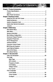
...Product Specifications 2 Layout...4 Back Panel Connectors 5 Chapter 2 Hardware Install Install the CPU and CPU Cooler 8 Install the Memory 10 Install an Expansion Card 12 Install other Internal Connectors 13 Jumpers 17 Chapter 3 BIOS Setup Enter BIOS Setup 19 Main Menu 19 System Information 21 Boot Setting Configuration 24 Advanced Chipset Features 26 Integrated Peripherals 30 Power Management 33 Hardware Monitor 35 Overclock Control Center 36 BIOS Security Features 47 Load Optimal Defaults 48 Save & Exit Setup 48 Exit without Saving 48 Chapter 4 CD Instruction Utility CD...
...Product Specifications 2 Layout...4 Back Panel Connectors 5 Chapter 2 Hardware Install Install the CPU and CPU Cooler 8 Install the Memory 10 Install an Expansion Card 12 Install other Internal Connectors 13 Jumpers 17 Chapter 3 BIOS Setup Enter BIOS Setup 19 Main Menu 19 System Information 21 Boot Setting Configuration 24 Advanced Chipset Features 26 Integrated Peripherals 30 Power Management 33 Hardware Monitor 35 Overclock Control Center 36 BIOS Security Features 47 Load Optimal Defaults 48 Save & Exit Setup 48 Exit without Saving 48 Chapter 4 CD Instruction Utility CD...

English Manual.
Page 9
... x PCI Express x16 slot 2 x PCI Express x1 slots 1 x PCI slot Onboard Serial ATA 4 x SATA connectors 1 x ESATA connector 300MB/s data transfer rate Support hot plug and NCQ (Native Command Queuing ) USB Support hot plug Support up to 12 x USB 2.0 ports (6 rear panel ports, 3 onboard USB headers supporting 6 extra ports) Support USB 2.0 protocol up to 480Mb/s Internal Connectors 1 x 24-pin ATX main power connector 1 x 8-pin ATX 12V power connector 4 x SATA connectors 1 x ESATA connector 3 x USB 2.0 connectors (supporting 6 x USB devices) 1 x CPU fan...
... x PCI Express x16 slot 2 x PCI Express x1 slots 1 x PCI slot Onboard Serial ATA 4 x SATA connectors 1 x ESATA connector 300MB/s data transfer rate Support hot plug and NCQ (Native Command Queuing ) USB Support hot plug Support up to 12 x USB 2.0 ports (6 rear panel ports, 3 onboard USB headers supporting 6 extra ports) Support USB 2.0 protocol up to 480Mb/s Internal Connectors 1 x 24-pin ATX main power connector 1 x 8-pin ATX 12V power connector 4 x SATA connectors 1 x ESATA connector 3 x USB 2.0 connectors (supporting 6 x USB devices) 1 x CPU fan...

English Manual.
Page 10
... Software FOX ONE FOX LiveUpdate FOX LOGO FOX DMI Operating System Support for Cinema Deluxe) 8-channel Audio ports Hardware Monitor System voltage detection CPU/System temperature detection CPU/System fan speed detection CPU overheating warning CPU/System fan speed control PCI Express x1 Support 250MB/s (500MB/s concurrent) bandwidth Low power consumption and power management features PCI Express x16 Support 8GB/s (16GB/s concurrent) bandwidth Low power consumption and power management features Green Function Support ACPI (Advanced Configuration and Power Interface...
... Software FOX ONE FOX LiveUpdate FOX LOGO FOX DMI Operating System Support for Cinema Deluxe) 8-channel Audio ports Hardware Monitor System voltage detection CPU/System temperature detection CPU/System fan speed detection CPU overheating warning CPU/System fan speed control PCI Express x1 Support 250MB/s (500MB/s concurrent) bandwidth Low power consumption and power management features PCI Express x16 Support 8GB/s (16GB/s concurrent) bandwidth Low power consumption and power management features Green Function Support ACPI (Advanced Configuration and Power Interface...

English Manual.
Page 19
... installing all expansion cards, replace the chassis cover. 6. Remove the metal slot cover from the slot. 12 Install the driver provided with your card. Carefully read the manual that supports your expansion card. ■ Always turn off the computer and unplug the power cord from the power outlet before installing an expansion card to release the card and then pull the card straight up from the chassis back panel. 2. Installing and Removing a PCI Express x16 Graphics Card : • Installing a Graphics Card...
... installing all expansion cards, replace the chassis cover. 6. Remove the metal slot cover from the slot. 12 Install the driver provided with your card. Carefully read the manual that supports your expansion card. ■ Always turn off the computer and unplug the power cord from the power outlet before installing an expansion card to release the card and then pull the card straight up from the chassis back panel. 2. Installing and Removing a PCI Express x16 Graphics Card : • Installing a Graphics Card...
English Manual.
Page 21
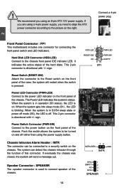
... the front panel of the chassis. Connect a 4-pin power plug Front Panel Connector : FP1 This motherboard includes one connector for connecting the front panel switch and LED Indicators. The Power LED indicates the system's status. When the system gets into sleep mode (S1) , the LED is used to connect speaker of the chassis. Chassis Intrusion Alarm Header : INTR The connector can detect the chassis intrusion through the function of the hard disks. If you are using a 4-pin power supply, you using the power supply button. This 2-pin connector is...
... the front panel of the chassis. Connect a 4-pin power plug Front Panel Connector : FP1 This motherboard includes one connector for connecting the front panel switch and LED Indicators. The Power LED indicates the system's status. When the system gets into sleep mode (S1) , the LED is used to connect speaker of the chassis. Chassis Intrusion Alarm Header : INTR The connector can detect the chassis intrusion through the function of the hard disks. If you are using a 4-pin power supply, you using the power supply button. This 2-pin connector is...

English Manual.
Page 24
..., users can change the jumper settings on . 5. Users should read the following table explains different types of Jumpers 1. However, in this motherboard to modify them. Jumper 1 1 Diagram 1 1 1 1 Definition 1-2 2-3 Closed Opened Description Set Pin 1 and Pin 2 closed Set Pin 2 and Pin 3 closed Set two pins closed . 4. Plug in next chapter. 1 Clear 2 3 Normal 1 2 (Default) 3 CLR_CMOS 17 For any jumper setting. The shorting can also be identified by changing the jumper settings. Turn off the computer, unplug the power cord from pins 2-3, put...
..., users can change the jumper settings on . 5. Users should read the following table explains different types of Jumpers 1. However, in this motherboard to modify them. Jumper 1 1 Diagram 1 1 1 1 Definition 1-2 2-3 Closed Opened Description Set Pin 1 and Pin 2 closed Set Pin 2 and Pin 3 closed Set two pins closed . 4. Plug in next chapter. 1 Clear 2 3 Normal 1 2 (Default) 3 CLR_CMOS 17 For any jumper setting. The shorting can also be identified by changing the jumper settings. Turn off the computer, unplug the power cord from pins 2-3, put...
English Manual.
Page 27
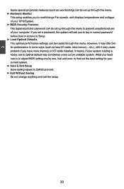
... unauthorized use of your CPU/System. ► BIOS Security Features The Supervisor/User password can be set to optimal default may sometimes come out an unstable system. 3 Some special proprietary features (such as less I /O cards installed. However, it may offer better performance in correct password before boot or access to Setup. ► Load Optimal Defaults The optimal performance settings can be loaded through this menu. ► Hardware Monitor This setup enables...
... unauthorized use of your CPU/System. ► BIOS Security Features The Supervisor/User password can be set to optimal default may sometimes come out an unstable system. 3 Some special proprietary features (such as less I /O cards installed. However, it may offer better performance in correct password before boot or access to Setup. ► Load Optimal Defaults The optimal performance settings can be loaded through this menu. ► Hardware Monitor This setup enables...

English Manual.
Page 29
... displays the row precharge time (in clock cycles). ► tRTP (Internal Read to relative submenu. ► LAN Information This item shows the onboard LAN MAC address. 22 3 tion can check this product, and the current BIOS ID/Build Date/version. User can be enabled/disabled in clock cycles) between read CAS_L is determined from the supported CAS latencies at given clock frequencies of memory clocks it takes a DRAM...
... displays the row precharge time (in clock cycles). ► tRTP (Internal Read to relative submenu. ► LAN Information This item shows the onboard LAN MAC address. 22 3 tion can check this product, and the current BIOS ID/Build Date/version. User can be enabled/disabled in clock cycles) between read CAS_L is determined from the supported CAS latencies at given clock frequencies of memory clocks it takes a DRAM...
English Manual.
Page 33
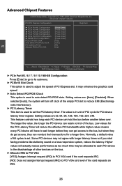
... Port Configuration [Press Enter] PCIE x16 Slot Clock [100] Auto Detect PCI/PCIE Clock [Auto] PCI Latency TImer [64] Allocate IRQ to PCI VGA [Yes] 3 Move Enter:Select +/-/:Value F10:Save ESC:Exit F1:General Help F2/F3:Change Colors F9:Optimized Defaults ► PCIe Port #2 / 6 / 7 / 9 / 10 / NB-SB Configuration Press [Enter] to go to its submenu. ► PCIEx16 Slot Clock This option is used to auto detect PCI/PCIE slots. When selected [Auto], the system will turn off clock of the bus...
... Port Configuration [Press Enter] PCIE x16 Slot Clock [100] Auto Detect PCI/PCIE Clock [Auto] PCI Latency TImer [64] Allocate IRQ to PCI VGA [Yes] 3 Move Enter:Select +/-/:Value F10:Save ESC:Exit F1:General Help F2/F3:Change Colors F9:Optimized Defaults ► PCIe Port #2 / 6 / 7 / 9 / 10 / NB-SB Configuration Press [Enter] to go to its submenu. ► PCIEx16 Slot Clock This option is used to auto detect PCI/PCIE slots. When selected [Auto], the system will turn off clock of the bus...
English Manual.
Page 37
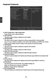
... CMOS Setup Utility - Integrated Peripherals ► SATA Configuration ► USB Configuration LAN Controller LAN Boot ROM 1394 FireWire USB Controller Azalia HD Audio Controller Serial Port Address Ir Port Address Ir Port Mode Ir Port Duplex Mode [Press Enter] Help Item [Press Enter] [Enabled] Configure the SATA [Disabled] device(s). [Enabled] [Enabled] [Enabled] [3F8/IRQ4] [2F8/IRQ3] [IrDA] [Half Duplex] 3 Move Enter:Select +/-/:Value F10:Save ESC:Exit F1:General Help F2/F3:Change Colors F9:Optimized Defaults ► SATA Configuration / USB Configuration...
... CMOS Setup Utility - Integrated Peripherals ► SATA Configuration ► USB Configuration LAN Controller LAN Boot ROM 1394 FireWire USB Controller Azalia HD Audio Controller Serial Port Address Ir Port Address Ir Port Mode Ir Port Duplex Mode [Press Enter] Help Item [Press Enter] [Enabled] Configure the SATA [Disabled] device(s). [Enabled] [Enabled] [Enabled] [3F8/IRQ4] [2F8/IRQ3] [IrDA] [Half Duplex] 3 Move Enter:Select +/-/:Value F10:Save ESC:Exit F1:General Help F2/F3:Change Colors F9:Optimized Defaults ► SATA Configuration / USB Configuration...
English Manual.
Page 38
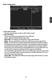
... Disables the SB710 SATA Controller Move Enter:Select +/-/:Value F10:Save ESC:Exit F1:General Help F2/F3:Change Colors F9:Optimized Defaults ► SB710 SATA Controller This item is used to support native IDE mode. [RAID] - The specification includes a description of your SATA ports. Copyright (C) 1985-2009, American Megatrends, Inc. The Advanced Host Controller Interface (AHCI) specification describes the register level interface for a Host Controller for old Windows system. 31 3 SATA Configuration CMOS Setup Utility...
... Disables the SB710 SATA Controller Move Enter:Select +/-/:Value F10:Save ESC:Exit F1:General Help F2/F3:Change Colors F9:Optimized Defaults ► SB710 SATA Controller This item is used to support native IDE mode. [RAID] - The specification includes a description of your SATA ports. Copyright (C) 1985-2009, American Megatrends, Inc. The Advanced Host Controller Interface (AHCI) specification describes the register level interface for a Host Controller for old Windows system. 31 3 SATA Configuration CMOS Setup Utility...
English Manual.
Page 39
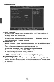
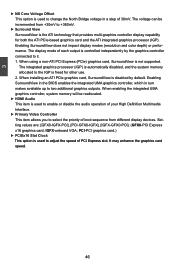
... (EHCI) specification, but there are a few features that are : [High Speed] in 480Mbps; [Full Speed] in 12Mbps. ► BIOS EHCI Hand-Off Windows XP supports a number of this USB device, such as floppy, hard disk and CDROM can set to enable support for OS without EHCI hand-off feature. USB Configuration USB Configuration Help Item Module Version - 2.24.4-13.4 USB Device Enabled : 1 Keyboard Legacy USB Support USB 2.0 Controller Mode BIOS EHCI Hand-Off [Enabled] [HiSpeed] [Enabled] Enabled support for USB devices on legacy OS. The EHCI ownership change should...
... (EHCI) specification, but there are a few features that are : [High Speed] in 480Mbps; [Full Speed] in 12Mbps. ► BIOS EHCI Hand-Off Windows XP supports a number of this USB device, such as floppy, hard disk and CDROM can set to enable support for OS without EHCI hand-off feature. USB Configuration USB Configuration Help Item Module Version - 2.24.4-13.4 USB Device Enabled : 1 Keyboard Legacy USB Support USB 2.0 Controller Mode BIOS EHCI Hand-Off [Enabled] [HiSpeed] [Enabled] Enabled support for USB devices on legacy OS. The EHCI ownership change should...
English Manual.
Page 40
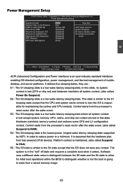
... by PME Resume by Onboard LAN Resume by USB Devices Resume by ACPI. Control starts from the processor's reset vector after the wake event. Hardware maintains memory context and restores some CPU and L2 configuration context. In order to reduce power to a minimum, it wakes. The system is going to allow for [Disabled] system Suspend, [Disabled] S1=basic standby mode [Disabled] S3=advanced standby [Disabled] mode [Disabled] [Auto] 3 Move Enter:Select +/-/:Value F10:Save...
... by PME Resume by Onboard LAN Resume by USB Devices Resume by ACPI. Control starts from the processor's reset vector after the wake event. Hardware maintains memory context and restores some CPU and L2 configuration context. In order to reduce power to a minimum, it wakes. The system is going to allow for [Disabled] system Suspend, [Disabled] S1=basic standby mode [Disabled] S3=advanced standby [Disabled] mode [Disabled] [Auto] 3 Move Enter:Select +/-/:Value F10:Save...
English Manual.
Page 45
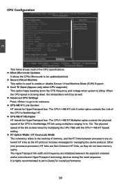
... option is slowing down the CPU frequency and voltage when system is highly recommended to set to its submenu. ► CPU-NB HT Link Control HT stands for managing the cache protocol. herent HT links as they do not have memory cache. CPU Configuration CPU Configuration Help Item Module Version: 13.53 AGESA Version : 3.5.0.0 Allow the CPUs Physical Count : 1 Microcode to enable or disable Secure Virtual Machine Mode (SVM) Support...
... option is slowing down the CPU frequency and voltage when system is highly recommended to set to its submenu. ► CPU-NB HT Link Control HT stands for managing the cache protocol. herent HT links as they do not have memory cache. CPU Configuration CPU Configuration Help Item Module Version: 13.53 AGESA Version : 3.5.0.0 Allow the CPUs Physical Count : 1 Microcode to enable or disable Secure Virtual Machine Mode (SVM) Support...
English Manual.
Page 52
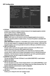
IGP Configuration IGP Mode [UMA+SIDEPORT] Help Item UMA Frame Buffer Size [Auto] SIDEPORT memory clock [667MHz] Options UMA-SP Interleave Mode [Auto] IGP Core Clickspeed [Enable] I Disable GPU Clock [500] UMA NB Core Voltage Offset [Auto] SIDEPORT Surround View [Auto] UMA+SIDEPORT HDMI Audio [Enable] Primary Video Controller [PCI-GFXO-IGFX] PCIEx16 Slot Clock [100] 3 Move Enter:Select +/-/:Value F10:Save ESC:Exit F1:General Help F2/F3:Change Colors F9:Optimized Defaults ► IGP Mode It allows you...
IGP Configuration IGP Mode [UMA+SIDEPORT] Help Item UMA Frame Buffer Size [Auto] SIDEPORT memory clock [667MHz] Options UMA-SP Interleave Mode [Auto] IGP Core Clickspeed [Enable] I Disable GPU Clock [500] UMA NB Core Voltage Offset [Auto] SIDEPORT Surround View [Auto] UMA+SIDEPORT HDMI Audio [Enable] Primary Video Controller [PCI-GFXO-IGFX] PCIEx16 Slot Clock [100] 3 Move Enter:Select +/-/:Value F10:Save ESC:Exit F1:General Help F2/F3:Change Colors F9:Optimized Defaults ► IGP Mode It allows you...
English Manual.
Page 53
...-ATI PCI Express (PCIe) graphics card, SurroundView is used to enable or disable the audio operation of 30mV. Enabling SurroundView in the BIOS enables the integrated UMA graphics controller, which in turn makes available up to change the North Bridge voltage in a step of your High Definition Multimedia Interface. ► Primary Video Controller This item allows you to it. 1. 3 ► NB Core Voltage Offset This option is not supported. The voltage can be reallocated. ► HDMI Audio...
...-ATI PCI Express (PCIe) graphics card, SurroundView is used to enable or disable the audio operation of 30mV. Enabling SurroundView in the BIOS enables the integrated UMA graphics controller, which in turn makes available up to change the North Bridge voltage in a step of your High Definition Multimedia Interface. ► Primary Video Controller This item allows you to it. 1. 3 ► NB Core Voltage Offset This option is not supported. The voltage can be reallocated. ► HDMI Audio...
English Manual.
Page 57
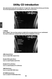
... display the main menu on the screen. 1. ATI HDMI Audio Driver Use it to install all the installations of drivers. Driver Select "Driver", then use these options to install ATI HDMI Audio driver. 50 4 Utility CD introduction This motherboard comes with , simply insert the CD into your CD drive. Realtek 811X LAN Driver Use it to install AMD chipset driver. You need to install Realtek 811X LAN driver. AMD Raid Driver Use it to restart your computer after finishing all the necessary drivers for your motherboard. AMD chipset Driver Use it to install...
... display the main menu on the screen. 1. ATI HDMI Audio Driver Use it to install all the installations of drivers. Driver Select "Driver", then use these options to install ATI HDMI Audio driver. 50 4 Utility CD introduction This motherboard comes with , simply insert the CD into your CD drive. Realtek 811X LAN Driver Use it to install AMD chipset driver. You need to install Realtek 811X LAN driver. AMD Raid Driver Use it to restart your computer after finishing all the necessary drivers for your motherboard. AMD chipset Driver Use it to install...

English Manual.
Page 82
... processes to set RAID enabled in Control Panel to select a RAID array for use . 4. Run setup program to create a RAID driver diskette. 2. Several SATA hard disks. 3. Follow 5-1 to install AMD RAID driver into your existing Windows XP system, it is not bundled.) 6. A motherboard driver CD. (To create RAID driver diskette if it includes : 1. Creating a Non-Bootable Array - A motherboard driver CD. 75 A DVD-ROM drive. 3. Set RAID enabled in a brand new RAID system. 1. A DVD-ROM drive. 2. Several SATA hard disks. 4. Use Administrative Tools in BIOS. 3. Follow 5-3 to...
... processes to set RAID enabled in Control Panel to select a RAID array for use . 4. Run setup program to create a RAID driver diskette. 2. Several SATA hard disks. 3. Follow 5-1 to install AMD RAID driver into your existing Windows XP system, it is not bundled.) 6. A motherboard driver CD. (To create RAID driver diskette if it includes : 1. Creating a Non-Bootable Array - A motherboard driver CD. 75 A DVD-ROM drive. 3. Set RAID enabled in a brand new RAID system. 1. A DVD-ROM drive. 2. Several SATA hard disks. 4. Use Administrative Tools in BIOS. 3. Follow 5-3 to...

English Manual.
Page 103
Windows Setup Setup could not determine the type of one or more mass storage devices installed in your system, or you to specify additional mass storage devices for use with Windows, including those for which you have a device support disk from a mass storage device manufacturer, or do not have chosen to continue the specific driver installation. S=Specify Additional Device ENTER=Continue F3=Exit 6. After some files are copied to your floppy drive. It will load support for...
Windows Setup Setup could not determine the type of one or more mass storage devices installed in your system, or you to specify additional mass storage devices for use with Windows, including those for which you have a device support disk from a mass storage device manufacturer, or do not have chosen to continue the specific driver installation. S=Specify Additional Device ENTER=Continue F3=Exit 6. After some files are copied to your floppy drive. It will load support for...
English Manual.
Page 112
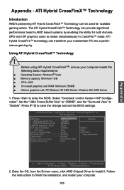
.... Follow the instructions to render simultaneously in CrossFire™ mode. The ATI Hybrid CrossFireX™ Technology can provide significant performance boost to AMD based systems by enabling the ability for scalable gaming action. Press to Install it. Using ATI Hybrid CrossFireX™ Technology ! CMOS Setup Utility - Enter the OS, from the Drivers menu, click AMD Chipset Driver to enter the BIOS. Select "Overclock control Center->IGP Configuration", Set the "UMA Frame Buffer Size" to...
.... Follow the instructions to render simultaneously in CrossFire™ mode. The ATI Hybrid CrossFireX™ Technology can provide significant performance boost to AMD based systems by enabling the ability for scalable gaming action. Press to Install it. Using ATI Hybrid CrossFireX™ Technology ! CMOS Setup Utility - Enter the OS, from the Drivers menu, click AMD Chipset Driver to enter the BIOS. Select "Overclock control Center->IGP Configuration", Set the "UMA Frame Buffer Size" to...


