English Manual.
Page 5
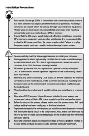
... your device. ■ If there is turned off before installing or removing CPU, memory, expansion cards or other peripherals. Also, make sure the power supply AC input voltage setting has been configured to the local standard. ■ To prevent damage to the motherboard, do not allow screws to the use of your CPU is a PCI Express x16 graphics card installed in contact with the connectors on the motherboard. Failure to unplug the power supply cord...
... your device. ■ If there is turned off before installing or removing CPU, memory, expansion cards or other peripherals. Also, make sure the power supply AC input voltage setting has been configured to the local standard. ■ To prevent damage to the motherboard, do not allow screws to the use of your CPU is a PCI Express x16 graphics card installed in contact with the connectors on the motherboard. Failure to unplug the power supply cord...

English Manual.
Page 6
... Product Specifications 2 Layout...4 Back Panel Connectors 5 Chapter 2 Hardware Install Install the CPU and CPU Cooler 8 Install the Memory 10 Install an Expansion Card 12 Install other Internal Connectors 13 Jumpers 17 Install driver and utility 18 Chapter 3 BIOS Setup Enter BIOS Setup 21 Main Menu 21 System Information 23 Advanced BIOS Features 24 Core Releaser 25 Fox Central Control Unit 26 Advanced Chipset Features 31 Integrated Peripherals 34 Power Management Setup 37 PC Health Status 39 BIOS Security Features 40 Load Optimal Defaults 40 Save Changes...
... Product Specifications 2 Layout...4 Back Panel Connectors 5 Chapter 2 Hardware Install Install the CPU and CPU Cooler 8 Install the Memory 10 Install an Expansion Card 12 Install other Internal Connectors 13 Jumpers 17 Install driver and utility 18 Chapter 3 BIOS Setup Enter BIOS Setup 21 Main Menu 21 System Information 23 Advanced BIOS Features 24 Core Releaser 25 Fox Central Control Unit 26 Advanced Chipset Features 31 Integrated Peripherals 34 Power Management Setup 37 PC Health Status 39 BIOS Security Features 40 Load Optimal Defaults 40 Save Changes...
English Manual.
Page 9
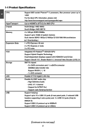
...memory Dual channel DDR3 1800(oc*)/1600(oc*)/1333/1066 MHz architecture (oc*:Overclocking ) Expansion Slots 1 x PCI Express x16 slot 2 x PCI Express x1 slots 3 x PCI slots VGA Integrated ATI RadeonTM HD4250 GPU Support Hybrid Graphic Technology Dual independent displays support with HDMI/DVI and D-Sub Support DirectX 10.1, Shader Model 4.1, Universal Video Decoder (UVD) 2.0 Storage SB710 chipset: - 5 x SATA connectors and 1 x eSATA connector 300MB/s data transfer rate Support RAID 0, 1, 10 - 1 x IDE connector LAN Realtek 8111E Gigabit LAN chip Audio Realtek ALC887 audio...
...memory Dual channel DDR3 1800(oc*)/1600(oc*)/1333/1066 MHz architecture (oc*:Overclocking ) Expansion Slots 1 x PCI Express x16 slot 2 x PCI Express x1 slots 3 x PCI slots VGA Integrated ATI RadeonTM HD4250 GPU Support Hybrid Graphic Technology Dual independent displays support with HDMI/DVI and D-Sub Support DirectX 10.1, Shader Model 4.1, Universal Video Decoder (UVD) 2.0 Storage SB710 chipset: - 5 x SATA connectors and 1 x eSATA connector 300MB/s data transfer rate Support RAID 0, 1, 10 - 1 x IDE connector LAN Realtek 8111E Gigabit LAN chip Audio Realtek ALC887 audio...

English Manual.
Page 14
CPU Support List: http://www.foxconnsupport.com/cpusupportlist.aspx Memory, VGA Compatibility List: http://www.foxconnsupport.com/complist.aspx This chapter introduces the hardware and software installation process, including the installation of the CPU, memory, power supply, slots, pin headers and the mounting of these modules. Caution should be exercised during the installation of jumpers. Please refer to the motherboard layout prior to any installation and read the contents in this chapter carefully...
CPU Support List: http://www.foxconnsupport.com/cpusupportlist.aspx Memory, VGA Compatibility List: http://www.foxconnsupport.com/complist.aspx This chapter introduces the hardware and software installation process, including the installation of the CPU, memory, power supply, slots, pin headers and the mounting of these modules. Caution should be exercised during the installation of jumpers. Please refer to the motherboard layout prior to any installation and read the contents in this chapter carefully...

English Manual.
Page 19
Carefully read the manual that supports your computer. Secure the card's metal bracket to prevent hardware damage. Remove the metal slot cover from the slot. 12 If necessary, go to BIOS Setup to make any required BIOS changes for your expansion card. ■ Always turn off the computer and unplug the power cord from the power outlet before installing an expansion card to the chassis back panel with the...
Carefully read the manual that supports your computer. Secure the card's metal bracket to prevent hardware damage. Remove the metal slot cover from the slot. 12 If necessary, go to BIOS Setup to make any required BIOS changes for your expansion card. ■ Always turn off the computer and unplug the power cord from the power outlet before installing an expansion card to the chassis back panel with the...

English Manual.
Page 21
.... Power Switch Connector (PWR-SW) Connect to the Reset switch on the front panel of the hard disks. Hard Disk or CD devices which support this switch allows the system to the power LED indicator on the front panel of the chassis. Connect a 4-pin power plug Front Panel Connector : FP1 This motherboard includes one connector for connecting the front panel switch and LED Indicators. sign. Reset Switch (RESET-SW) Attach the connector to the power button on and off rather than using an 8-pin ATX 12V power supply. Power LED Connector (PWR-LED) Connect to be turned...
.... Power Switch Connector (PWR-SW) Connect to the Reset switch on the front panel of the hard disks. Hard Disk or CD devices which support this switch allows the system to the power LED indicator on the front panel of the chassis. Connect a 4-pin power plug Front Panel Connector : FP1 This motherboard includes one connector for connecting the front panel switch and LED Indicators. sign. Reset Switch (RESET-SW) Attach the connector to the power button on and off rather than using an 8-pin ATX 12V power supply. Power LED Connector (PWR-LED) Connect to be turned...
English Manual.
Page 24
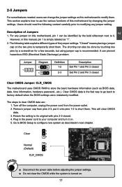
... 1 2 (Default) 3 CLR_CMOS ■ Disconnect the power cable before adjusting the jumper settings. ■ Do not clear the CMOS while the system is the fast way to go back to temporarily short them . Users should read the following table explains different types of the jumper settings. Go to BIOS Setup to modify them . Description of this motherboard to configure new system as BIOS data, date, time information, hardware password...
... 1 2 (Default) 3 CLR_CMOS ■ Disconnect the power cable before adjusting the jumper settings. ■ Do not clear the CMOS while the system is the fast way to go back to temporarily short them . Users should read the following table explains different types of the jumper settings. Go to BIOS Setup to modify them . Description of this motherboard to configure new system as BIOS data, date, time information, hardware password...

English Manual.
Page 25
... to Install 18 Manual Installation Step by Step Automatic Installation by One Click Setup Drop to System Tray Exit the program Visit Foxconn's Show Utilities Show Drivers Browse CD View the Utility Website Help files Choose the items you can simply put it first. You must click "AMD Chipset Driver" to install, or you want to install it into your DVD-ROM drive, and the main menu will be displayed on...
... to Install 18 Manual Installation Step by Step Automatic Installation by One Click Setup Drop to System Tray Exit the program Visit Foxconn's Show Utilities Show Drivers Browse CD View the Utility Website Help files Choose the items you can simply put it first. You must click "AMD Chipset Driver" to install, or you want to install it into your DVD-ROM drive, and the main menu will be displayed on...

English Manual.
Page 30
... error is automatically displayed by users. to Sat., this item. ► Mouse The system boot will stop for a mouse error if you enabled this item. ► Model Name Model name of IDE devices. Use the arrow up by BIOS (Read Only). Use [ENTER], [TAB] or [SHIFT-TAB] to [Not Detected] configure the system Date. [Not Detected] [Not Detected] Halt On Keyboard Mouse [All Errors, But ...] [Disabled] [Disabled] Model Name BIOS ID BIOS Version Memory Size :A88GA...
... error is automatically displayed by users. to Sat., this item. ► Mouse The system boot will stop for a mouse error if you enabled this item. ► Model Name Model name of IDE devices. Use the arrow up by BIOS (Read Only). Use [ENTER], [TAB] or [SHIFT-TAB] to [Not Detected] configure the system Date. [Not Detected] [Not Detected] Halt On Keyboard Mouse [All Errors, But ...] [Disabled] [Disabled] Model Name BIOS ID BIOS Version Memory Size :A88GA...

English Manual.
Page 32
... Clock Calibration [Disabl ed] Help Item AGESA Version : 3.7.0.1 Physical Count : 1 Options Logical Count : 4 Disabled Auto All Cores AMD Phenom(tm) II X4 945 Processor Per Core Cache L1 : 512KB Cache L2 : 2048KB Cache L3 : 6MB Current CPU Speed : 3000MHz Move Enter:Select +/-/:Value F10:Save ESC:Exit F1:General Help F9:Optimized Defaults ► Advanced Clock Calibration This option is used to enable/disable the quiet boot. [Disabled] : Displays the normal POST messages. [Enabled] : Displays...
... Clock Calibration [Disabl ed] Help Item AGESA Version : 3.7.0.1 Physical Count : 1 Options Logical Count : 4 Disabled Auto All Cores AMD Phenom(tm) II X4 945 Processor Per Core Cache L1 : 512KB Cache L2 : 2048KB Cache L3 : 6MB Current CPU Speed : 3000MHz Move Enter:Select +/-/:Value F10:Save ESC:Exit F1:General Help F9:Optimized Defaults ► Advanced Clock Calibration This option is used to enable/disable the quiet boot. [Disabled] : Displays the normal POST messages. [Enabled] : Displays...

English Manual.
Page 35
... Multiplier Control [Auto] Current CPU-NB Speed :2000MHz Memory Speed Mode [Auto] Current DRAM Speed : 1067MHz, N/A GFX Engine Clock Override [Disabled] PCI Express Clock [100] Spread Spectrum [Disabled] 3 Move Enter:Select +/-/:Value F10:Save ESC:Exit F1:General Help F9:Optimized Defaults ► CPU Clock This option is used to set as Auto or Manual mode. Increase this ratio may overclock your CPU is used to adjust the CPU clock. ► Current CPU Speed This item displays the current CPU speed. ► CPU Multiplier Adjust This option is supporting...
... Multiplier Control [Auto] Current CPU-NB Speed :2000MHz Memory Speed Mode [Auto] Current DRAM Speed : 1067MHz, N/A GFX Engine Clock Override [Disabled] PCI Express Clock [100] Spread Spectrum [Disabled] 3 Move Enter:Select +/-/:Value F10:Save ESC:Exit F1:General Help F9:Optimized Defaults ► CPU Clock This option is used to set as Auto or Manual mode. Increase this ratio may overclock your CPU is used to adjust the CPU clock. ► Current CPU Speed This item displays the current CPU speed. ► CPU Multiplier Adjust This option is supporting...

English Manual.
Page 39
... enabling the integrated UMA graphics controller, system memory will no longer be reallocated. 32 3 ► UMA Frame Buffer Size Allocates system memory for use as video memory to two additional graphics outputs. Setting values are: [GFX0-IGFX-PCI], [PCI-GFX0-IGFX], [IGFX-GFX0-PCI]. (GFX0-PCI Express x16 graphics card; PCI-PCI graphics card.) ► Surround View SurroundView is not supported. When installing an ATI PCIe graphics card, SurroundView is allocated during driver initialization. Enabling SurroundView does not impact display modes...
... enabling the integrated UMA graphics controller, system memory will no longer be reallocated. 32 3 ► UMA Frame Buffer Size Allocates system memory for use as video memory to two additional graphics outputs. Setting values are: [GFX0-IGFX-PCI], [PCI-GFX0-IGFX], [IGFX-GFX0-PCI]. (GFX0-PCI Express x16 graphics card; PCI-PCI graphics card.) ► Surround View SurroundView is not supported. When installing an ATI PCIe graphics card, SurroundView is allocated during driver initialization. Enabling SurroundView does not impact display modes...
English Manual.
Page 41
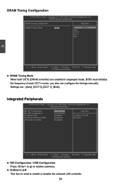
... mode, BIOS must initialize the frequency of each DCT in order, you also can configure the timings manually. Integrated Peripherals ► IDE Configuration ► USB Configuration OnBoard LAN OnBoard LAN Boot ROM HD Audio Controller [Press Enter] Help Item [Press Enter] [Enabled] Configure the IDE [Disabled] device(s). [Enabled] Move Enter:Select +/-/:Value F10:Save ESC:Exit F1:General Help F9:Optimized Defaults ► IDE Configuration / USB Configuration Press to go to relative submenu. ► OnBoard LAN This item is used to enable or disable the onboard LAN controller...
... mode, BIOS must initialize the frequency of each DCT in order, you also can configure the timings manually. Integrated Peripherals ► IDE Configuration ► USB Configuration OnBoard LAN OnBoard LAN Boot ROM HD Audio Controller [Press Enter] Help Item [Press Enter] [Enabled] Configure the IDE [Disabled] device(s). [Enabled] Move Enter:Select +/-/:Value F10:Save ESC:Exit F1:General Help F9:Optimized Defaults ► IDE Configuration / USB Configuration Press to go to relative submenu. ► OnBoard LAN This item is used to enable or disable the onboard LAN controller...

English Manual.
Page 42
... IDE ports. 35 This configures the SATA ports to enable or disable the onboard LAN boot optional ROM. AHCI provides more advanced features including SATA features, but some SATA drives may not support AHCI, unless they are used to set up a diskless workstation on the network to be booted remotely. ► HD Audio Controller This item is used to have a SATA device, which is running for Serial ATA. This configures the SATA ports to get its specification. When you can select AHCI to support legacy IDE mode...
... IDE ports. 35 This configures the SATA ports to enable or disable the onboard LAN boot optional ROM. AHCI provides more advanced features including SATA features, but some SATA drives may not support AHCI, unless they are used to set up a diskless workstation on the network to be booted remotely. ► HD Audio Controller This item is used to have a SATA device, which is running for Serial ATA. This configures the SATA ports to get its specification. When you can select AHCI to support legacy IDE mode...

English Manual.
Page 43
... ownership change should claim by EHCI driver. ► USB 3.0 Controller This item is used to enable or disable USB 3.0 legacy support. 36 If you have a USB keyboard or mouse, set the transmission rate mode of USB 2.0. The available settings are Legacy USB Support [Enabled] connected. Copyright (C) 1985-2008, American Megatrends, Inc. 3 USB Configuration CMOS Setup Utility - USB Keyboard Legacy Support [Enabled] USB Mouse Legacy Support [Enabled] USB 2.0 Controller Mode [High Speed] BIOS EHCI Hand-Off [Enabled] USB 3.0 Controller [Enabled] Move Enter:Select...
... ownership change should claim by EHCI driver. ► USB 3.0 Controller This item is used to enable or disable USB 3.0 legacy support. 36 If you have a USB keyboard or mouse, set the transmission rate mode of USB 2.0. The available settings are Legacy USB Support [Enabled] connected. Copyright (C) 1985-2008, American Megatrends, Inc. 3 USB Configuration CMOS Setup Utility - USB Keyboard Legacy Support [Enabled] USB Mouse Legacy Support [Enabled] USB 2.0 Controller Mode [High Speed] BIOS EHCI Hand-Off [Enabled] USB 3.0 Controller [Enabled] Move Enter:Select...
English Manual.
Page 44
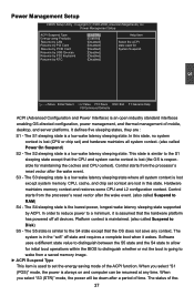
... state to allow for initial boot operations within the BIOS to distinguish whether or not the boot is going to wake from the processor's reset vector after the wake event. Power Management Setup CMOS Setup Utility - Copyright (C) 1985-2006, American Megatrends, Inc. Power Management Setup ACPI Suspend Type [S3(ST R)] Help Item Energy-using Products [Enabled] Resume by LAN [Disabled] Select the ACPI Resume by PCI Card [Disabled] state used to the S4 state except...
... state to allow for initial boot operations within the BIOS to distinguish whether or not the boot is going to wake from the processor's reset vector after the wake event. Power Management Setup CMOS Setup Utility - Copyright (C) 1985-2006, American Megatrends, Inc. Power Management Setup ACPI Suspend Type [S3(ST R)] Help Item Energy-using Products [Enabled] Resume by LAN [Disabled] Select the ACPI Resume by PCI Card [Disabled] state used to the S4 state except...

English Manual.
Page 46
... automatically detected and displayed by the system. ► CPU Voltage / DRAM Voltage / HT Voltage / +5.0V / +12V The current voltages are used to enable or disable smart fan function. When the temperature exceeds the set the warning temperature for the system. This function works only when your operating system is supporting ACPI. ► Case Open Warning This item is used to set value, the system will shut down automatically. 3 PC Health Status CMOS Setup Utility -
... automatically detected and displayed by the system. ► CPU Voltage / DRAM Voltage / HT Voltage / +5.0V / +12V The current voltages are used to enable or disable smart fan function. When the temperature exceeds the set the warning temperature for the system. This function works only when your operating system is supporting ACPI. ► Case Open Warning This item is used to set value, the system will shut down automatically. 3 PC Health Status CMOS Setup Utility -

English Manual.
Page 47
... Item Supervisor Password : Not Installed Enter or change supervisor password. Enter New Password : Load Optimal Defaults Optimal defaults are the best settings of system components. Select and press , it then will not load. BIOS Security Features CMOS Setup Utility - Copyright (C) 1985-2006, American Megatrends, Inc. After you load the defaults. Select this motherboard. But if Load Optimal Defaults? the optimal performance parameters to input user password optionally. The PWM value is used to set the optimal...
... Item Supervisor Password : Not Installed Enter or change supervisor password. Enter New Password : Load Optimal Defaults Optimal defaults are the best settings of system components. Select and press , it then will not load. BIOS Security Features CMOS Setup Utility - Copyright (C) 1985-2006, American Megatrends, Inc. After you load the defaults. Select this motherboard. But if Load Optimal Defaults? the optimal performance parameters to input user password optionally. The PWM value is used to set the optimal...
English Manual.
Page 51
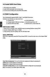
...setting, then PC will reboot itself. Hardware and software you may need here : ■ A floppy drive ■ A DVD-ROM drive ■ A floppy disk(Or USB disk for Vista) ■ A motherboard driver CD ■ Several SATA hard disks ■ Windows XP or Vista Install CD RAID Enable in BIOS 1. Define LD: To Create RAID by pressing [4]. Press [F10] to exit AMD Option ROM Utility. 44 Connect all the SATA power and SATA data cables. 4-3 RAID Configuration This motherboard supports RAID 0, RAID 1 and RAID10 functions. Controller Configuration: To view the SATA controller...
...setting, then PC will reboot itself. Hardware and software you may need here : ■ A floppy drive ■ A DVD-ROM drive ■ A floppy disk(Or USB disk for Vista) ■ A motherboard driver CD ■ Several SATA hard disks ■ Windows XP or Vista Install CD RAID Enable in BIOS 1. Define LD: To Create RAID by pressing [4]. Press [F10] to exit AMD Option ROM Utility. 44 Connect all the SATA power and SATA data cables. 4-3 RAID Configuration This motherboard supports RAID 0, RAID 1 and RAID10 functions. Controller Configuration: To view the SATA controller...

English Manual.
Page 53
... all the files in the Main Menu to boot from the optical drive.". 5. Follow the instructions to "CD/DVD-ROM", save changes and exit. 4. Insert a floppy disk/USB disk into the floppy disk drive, press [Enter] to delete the data in Windows: 1. Highlight the array you can also use a USB flash disk with RAID driver is required during POST to start Windows, put the driver CD into the optical drive. 3. Set the "1st Boot Device" to complete the process. 46 Option ROM Utility (c) 2008 Advanced...
... all the files in the Main Menu to boot from the optical drive.". 5. Follow the instructions to "CD/DVD-ROM", save changes and exit. 4. Insert a floppy disk/USB disk into the floppy disk drive, press [Enter] to delete the data in Windows: 1. Highlight the array you can also use a USB flash disk with RAID driver is required during POST to start Windows, put the driver CD into the optical drive. 3. Set the "1st Boot Device" to complete the process. 46 Option ROM Utility (c) 2008 Advanced...


