User manual
Page 5
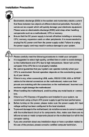
...is a PCI Express x16 graphics card installed in order to avoid damage to the motherboard and CPU due to unplug the AC power cord from the power supply outlet. Also, make sure their pinouts are uncertain about any metal leads or connec- Please wear an electrostatic discharge (ESD) wrist... the CPU fan is not properly installed. ■ We cannot guarantee that the DC power supply is suggested to select high-quality, certified fans in your system, we recommend using a 24-pin ATX power supply to get the best performance. ■ Before turning on the motherboard. Normally it comes...
...is a PCI Express x16 graphics card installed in order to avoid damage to the motherboard and CPU due to unplug the AC power cord from the power supply outlet. Also, make sure their pinouts are uncertain about any metal leads or connec- Please wear an electrostatic discharge (ESD) wrist... the CPU fan is not properly installed. ■ We cannot guarantee that the DC power supply is suggested to select high-quality, certified fans in your system, we recommend using a 24-pin ATX power supply to get the best performance. ■ Before turning on the motherboard. Normally it comes...

User manual
Page 14
... to any installation and read the contents in this chapter carefully. This chapter introduces the hardware installation process, including the installation of the CPU, memory, power supply, slots, pin headers and the mounting of these modules. Caution should be exercised during the installation of jumpers.
... to any installation and read the contents in this chapter carefully. This chapter introduces the hardware installation process, including the installation of the CPU, memory, power supply, slots, pin headers and the mounting of these modules. Caution should be exercised during the installation of jumpers.
User manual
Page 15
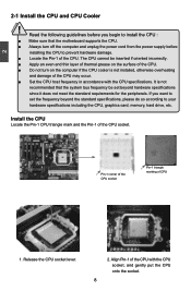
... even and thin layer of thermal grease on the surface of the CPU. ■ Do not turn off the computer and unplug the power cord from the power supply before installing the CPU to set beyond the standard specifications, please do so according to your hardware specifications including the CPU, graphics card, memory...
... even and thin layer of thermal grease on the surface of the CPU. ■ Do not turn off the computer and unplug the power cord from the power supply before installing the CPU to set beyond the standard specifications, please do so according to your hardware specifications including the CPU, graphics card, memory...
User manual
Page 20
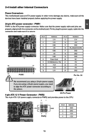
... you are properly aligned with the connector on the motherboard. 2 2-4 Install other Internal Connectors Power Connectors This motherboard uses an ATX power supply. We recommend you need to align the ATX power connector according to the picture. Firmly plug the power supply cable into the connector and make sure all the devices have been installed properly...
... you are properly aligned with the connector on the motherboard. 2 2-4 Install other Internal Connectors Power Connectors This motherboard uses an ATX power supply. We recommend you need to align the ATX power connector according to the picture. Firmly plug the power supply cable into the connector and make sure all the devices have been installed properly...

User manual
Page 22
...sleep mode (S1) , the LED is pressed. When the system is in operation (S0 status), the LED is on and off rather than using the power supply button. +5V 1 EMPTY 2 SPDIF_OUT 3 GND 4 SPDIF_OUT 12 + + HDD-LED - RESET-SW PWR-SW NC EMPTY 9 10 FP1 Serial ATA Connectors... allows up to the chassis front panel IDE indicator LED. Front Panel Connector : FP1 This motherboard includes one connector for S/PDIF output. The Power LED indicates the system's status. 2 S/PDIF Connector : SPDIF_OUT The connector is used to connect with +/- This 2-pin connector is off mode...
...sleep mode (S1) , the LED is pressed. When the system is in operation (S0 status), the LED is on and off rather than using the power supply button. +5V 1 EMPTY 2 SPDIF_OUT 3 GND 4 SPDIF_OUT 12 + + HDD-LED - RESET-SW PWR-SW NC EMPTY 9 10 FP1 Serial ATA Connectors... allows up to the chassis front panel IDE indicator LED. Front Panel Connector : FP1 This motherboard includes one connector for S/PDIF output. The Power LED indicates the system's status. 2 S/PDIF Connector : SPDIF_OUT The connector is used to connect with +/- This 2-pin connector is off mode...


