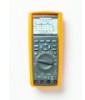
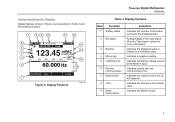
Fluke 287 and 289 Multimeter Users Manual
Page 1
All rights reserved. All product names are trademarks of their respective companies. Users Manual Specifications subject to change without notice. ® 287/289 True-rms Digital Multimeters June 2007, Rev. 1, 7/08 © 2007, 2008 Fluke Corporation.
Fluke 287 and 289 Multimeter Users Manual
Page 11
The descriptions and instructions in this manual apply to the model 289 and model 287 True-rms Digital Multimeters (hereafter referred to the insulation surrounding the connectors. 1 XWWarning To avoid possible electric shock or personal injury, follow these guidelines: • Use this Meter ... specified in this manual or the protection provided by the Meter might be impaired. • Do not use the Meter, inspect the case. Contacting Fluke To contact Fluke, call: USA: 1-888-993-5853 Canada : 1-800-363-5853 Europe : +31 402-675-200 Japan: +81-3-3434-0181 Singapore : +65-738-5655 Anywhere...
Fluke 287 and 289 Multimeter Users Manual
Page 13
True-rms Digital Multimeters Hazardous Voltage • Do not remove batteries while the Meter is turned on or a signal is displayed. 3 • Use proper protective equipment, as required by ... areas. • Comply with local and national safety requirements when working in circuits that could be damaged by this mode's low impedance (≈3 kΩ). (Model 289 only) Hazardous Voltage To alert you to the presence of a potentially hazardous voltage, when the Meter detects a voltage ≥30 V or a voltage overload (OL), the...
Fluke 287 and 289 Multimeter Users Manual
Page 15
Figure 1. Push Buttons est02.emf True-rms Digital Multimeters Features Table 2. Cursor buttons select an item in a menu, adjust display contrast, scroll through all ranges. Also accesses AutoHold. To return to Meter circuits. Understanding ...
Fluke 287 and 289 Multimeter Users Manual
Page 17
... 14 Crest Factor 3 5 mVDC Auto Range 0 100 200 300 400 500 VAC 15 2 60.000 Hz 16 AutoHOLD Save 1 Setup Figure 2. Display Features est01.eps True-rms Digital Multimeters Features Table 3. Analog display of the input signal (See the "Bar Graph" section for more information). Indicates activity over the communication link. Indicates a negative reading.
Fluke 287 and 289 Multimeter Users Manual
Page 19
... display (upper half of the page area) is where the most important value of the selected function is not already shown in the secondary display. True-rms Digital Multimeters Features 9 In addition, the minimeasurement display will appear in the primary display with frequency measurement selected in Vac, the frequency value will flash, if z (for...
Fluke 287 and 289 Multimeter Users Manual
Page 21
... functions except current use the A and COM terminals. COM Return terminal for voltage, continuity, resistance, diode test, conductance, capacitance, frequency, temperature, period, and dutycycle measurements. True-rms Digital Multimeters Features Table 5. Current between 0 and 10 A use the W and COM input terminals. The two current input terminals (A and mA/μA) are used as follows: Current...
Fluke 287 and 289 Multimeter Users Manual
Page 23
... is enabled. The Meter displays a message if the battery level will continue to flash to indicate the Meter is enabled, press R to the lowest range. True-rms Digital Multimeters Selecting the Range Selecting the Range The Meter's selected range is removed or inserted into a current input jack. • The Meter changes range • IR...
Fluke 287 and 289 Multimeter Users Manual
Page 25
... while MIN MAX record, peak record, or a recording session is plugged into the mA/μA or A terminal, but the data acquisition continues in the background. True-rms Digital Multimeters Input Alert™ Feature The information revealed through the Meter's current terminals is not in the Peak, MIN MAX, or Record modes. Pressing H again updates...
Fluke 287 and 289 Multimeter Users Manual
Page 27
... change function to be lost. See the "Setting Backlight and Auto Off Timeouts" section for more information on the Smoothing mode to display a steadier reading. True-rms Digital Multimeters Capturing Minimum and Maximum Values 8:10pm 06/07/07 Min Max 119.81 VAC Maximum Auto Range 127.09 VAC 500 VAC 00:03:17...
Fluke 287 and 289 Multimeter Users Manual
Page 29
... mode after a period of time set for more information on the battery saver mode. Peak capture can be ended by pressing the softkey labeled Stop. True-rms Digital Multimeters Capturing Peak Values 19 The summary information in the display freezes and the softkeys change function to identify one record from another name assigned. Therefore...
Fluke 287 and 289 Multimeter Users Manual
Page 31
... V and mV while in relative dBm or dBv mode does not disable the dB measurement. In addition, the two relative modes are available in the True-rms Digital Multimeters Making Relative Measurements secondary display. In relative or relative percent mode, the softkey label for REL %. The measurement value at the time that either the...
Fluke 287 and 289 Multimeter Users Manual
Page 33
During LoZ measurements, the Meter's range is therefore disabled as well. There are no additional modes for Voltage Measurements (Model 289 only) W Caution Do not use a reference impedance (resistance) to calculate a dB value based on 1 milliwatt. The Meter displays the ac ...with the frequency measurement. See the "Setting a Custom dBm Reference" section later in circuits that could be damaged by this manual. 8:10pm True-rms Digital Multimeters Making Measurements 06/13/07 41.83 dBm Auto Range 0 100 200 300 400 500 VAC 123.45 VAC 1000 Reference Menu Save Ref ...
Fluke 287 and 289 Multimeter Users Manual
Page 35
..., press the softkey labeled Menu. The bar graph for dc voltage measurements is a zero-centered bar graph. Refer to the appropriate section in Figure 12. True-rms Digital Multimeters Making Measurements 8:10pm 06/13/07 9.752 VDC Auto Range -50 -40 -30 -20 -10 0 10 20 30 40 50 VDC Menu Save Setup V est09...
Fluke 287 and 289 Multimeter Users Manual
Page 37
.... For AC+DC, ranging is controlled by the underlying values of the ac and dc signals and not by the sum of the present range. True-rms Digital Multimeters Making Measurements 27 only when both the ac and dc signals drop below 10% of the AC+DC calculation. To exit the AC+DC mode...
Fluke 287 and 289 Multimeter Users Manual
Page 39
...avoid possible damage to the meter or to help with the present offset value. Now all high-voltage capacitors before measuring resistance. offset. True-rms Digital Multimeters Making Measurements Keep the following in the offset or switch between the probe tips, the measured value of items that can add 0.1 ...function includes modes to the equipment under test. To test the leads, touch the probe tips together and read the resistance of the digits or the polarity sign. Use 6 and 5 to resistance measurements. Use 7 and 8 to the circuit under test, disconnect circuit power...
Fluke 287 and 289 Multimeter Users Manual
Page 41
...than 8 % of full scale for the 500 Ω range and less that 4 % for continuity transitions that are very short, the slow True-rms Digital Multimeters Making Measurements measurement response of a complete path for Continuity W Caution To avoid possible damage to the meter or to S and set up to ... reading, an open/short indicator, and a beeper. Testing for current flow. Short Open Figure 16. Using the Y Function (Model 289 Only) W Caution To avoid damaging the circuit under test, disconnect circuit power and discharge all high-voltage capacitors before testing continuity.
Fluke 287 and 289 Multimeter Users Manual
Page 43
... always enabled when continuity mode if first entered. This beeper selection, Beep on Short or Beep on shorts or opens, press the softkey labeled Menu. True-rms Digital Multimeters Making Measurements 33 Move the menu selector to the menu item labeled Beeper and press the softkey labeled Beeper.
Fluke 287 and 289 Multimeter Users Manual
Page 45
... all high-voltage capacitors before measuring capacitance. Measuring Capacitance W Caution To avoid possible damage to the meter or to microfarad (μF) range. Capacitance is discharged. True-rms Digital Multimeters Making Measurements 8:10pm 06/13/07 26.52 Auto Range 100 uF Menu Save Setup + est15.eps Figure 19. Capacitance Measurement 35 The Meter measures...
Fluke 287 and 289 Multimeter Users Manual
Page 47
Diode Testing est16.eps 37 True-rms Digital Multimeters Making Measurements 8:10pm 06/13/07 .567 VDC Manual Range 0 1 2 3 4 5 VDC Menu Save Setup Typical Reading Forward Bias + 8:10pm 06/13/07 OL VDC Manual Range 0 1 2 3 4 5 VDC Menu Save Setup Reverse Bias + Figure 20.