Fluke 1623 and 1625 Geo Earth Ground Testers Datasheet
Page 5
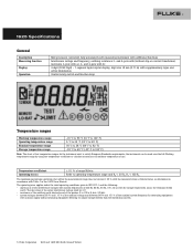
...frequency for measuring equipment with a mains supply and/or measuring equipment deriving its output voltage directly from the distribution system. 5 Fluke Corporation 1623 and 1625 GEO Earth Ground Testers Temperature coefficient ± 0.1 % of range/Kelvin Operating errors Refer to calculate accuracy at the ambient ...) and S. The rms value of 400 Hz, 60 Hz, 50 Hz, 162/3 Hz or with Table 1 in the 1625 Users Manual. 1625 Specifications General Description Measuring function Display Operation Microprocessor controlled, fully automated earth measuring instrument with ac, 2-
...frequency for measuring equipment with a mains supply and/or measuring equipment deriving its output voltage directly from the distribution system. 5 Fluke Corporation 1623 and 1625 GEO Earth Ground Testers Temperature coefficient ± 0.1 % of range/Kelvin Operating errors Refer to calculate accuracy at the ambient ...) and S. The rms value of 400 Hz, 60 Hz, 50 Hz, 162/3 Hz or with Table 1 in the 1625 Users Manual. 1625 Specifications General Description Measuring function Display Operation Microprocessor controlled, fully automated earth measuring instrument with ac, 2-

FE 1625 Users Manual
Page 1
® 1625 Earth/Ground Tester Users Manual January 2006 © 2006 Fluke Corporation, All rights reserved. Printed in USA All product names are trademarks of their respective companies.
® 1625 Earth/Ground Tester Users Manual January 2006 © 2006 Fluke Corporation, All rights reserved. Printed in USA All product names are trademarks of their respective companies.

FE 1625 Users Manual
Page 4
... 61 Recalibration 62 Storage 62 Specifications 64 Principle of Operation 65 Purpose 65 Operation 68 Settings on the Tester 69 Applications 70 Description of Interference - 1625 Users Manual Measurement of Displays 72 ii
... 61 Recalibration 62 Storage 62 Specifications 64 Principle of Operation 65 Purpose 65 Operation 68 Settings on the Tester 69 Applications 70 Description of Interference - 1625 Users Manual Measurement of Displays 72 ii

FE 1625 Users Manual
Page 6
1625 Users Manual iv
1625 Users Manual iv

FE 1625 Users Manual
Page 8
1625 Users Manual vi
1625 Users Manual vi

FE 1625 Users Manual
Page 10
1625 Users Manual Notes • The terms earth and earthing also refer to Appendix A for a complete set of operating information including specifications. • Selective measurements are described in the main section of this manual. • For stakeless earth resistance measurements, the EI-1625 must be purchased. (The EI-1625 comes standard with the 1625 Kit). Fluke 1625 Earth/Ground Tester...
1625 Users Manual Notes • The terms earth and earthing also refer to Appendix A for a complete set of operating information including specifications. • Selective measurements are described in the main section of this manual. • For stakeless earth resistance measurements, the EI-1625 must be purchased. (The EI-1625 comes standard with the 1625 Kit). Fluke 1625 Earth/Ground Tester...

FE 1625 Users Manual
Page 11
... Transformer (inducing) 12.7 Inch (320mm) Spilt Core Transformer 2-3 Wire Adapter Cable for 1625 for EI162AC Current Transformer Earth Stake Cable Reel w/25m Wire Cable Reel w/50m Wire 1625 Users Manual Item/Part Number Fluke-1625 Fluke-1625 Kit Fluke-162x-7001 ES-162P3 ES-162P4 EI-1625 EI-162X 2539195 EI-162AC EI-162BN 2577171 2539121 2539100 2539117 2560348 3 Earth...
... Transformer (inducing) 12.7 Inch (320mm) Spilt Core Transformer 2-3 Wire Adapter Cable for 1625 for EI162AC Current Transformer Earth Stake Cable Reel w/25m Wire Cable Reel w/50m Wire 1625 Users Manual Item/Part Number Fluke-1625 Fluke-1625 Kit Fluke-162x-7001 ES-162P3 ES-162P4 EI-1625 EI-162X 2539195 EI-162AC EI-162BN 2577171 2539121 2539100 2539117 2560348 3 Earth...
FE 1625 Users Manual
Page 12
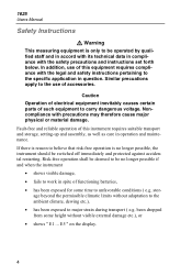
... to be no longer possible, the instrument should be switched off immediately and protected against accidental restarting. stor- Similar precuations apply to carry dangerous voltage. 1625 Users Manual Safety Instructions W Warning This measuring equipment is only to be operated by qualified staff and in accord with its technical data in operation and maintenance...
... to be no longer possible, the instrument should be switched off immediately and protected against accidental restarting. stor- Similar precuations apply to carry dangerous voltage. 1625 Users Manual Safety Instructions W Warning This measuring equipment is only to be operated by qualified staff and in accord with its technical data in operation and maintenance...

FE 1625 Users Manual
Page 14
... measure lightning protection systems without seperating the overhead earth wires or earth strips at the bottom of earthing resistance measurements. 1625 Users Manual General Microprocessor controlled universal earth resistance meter with the code programmable and customer defined special functions, e.g. Additional Accessories An external current transformer with a transformation ratio ...
... measure lightning protection systems without seperating the overhead earth wires or earth strips at the bottom of earthing resistance measurements. 1625 Users Manual General Microprocessor controlled universal earth resistance meter with the code programmable and customer defined special functions, e.g. Additional Accessories An external current transformer with a transformation ratio ...
FE 1625 Users Manual
Page 16
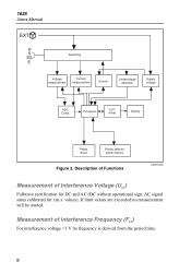
... derived from the period time. 8 Measurement of Interference Voltage (UST) Fullwave rectification for DC and AC (DC without operational sign, AC signal sinus calibrated for r.m.s. 1625 Users Manual EXT H S ES E Switching Voltage measurement Current measurement Source Undervoltage detection Supply voltage ADC Comp Processor LCD driver Display Relais driver Rotary selector switch buttons Figure 2.
... derived from the period time. 8 Measurement of Interference Voltage (UST) Fullwave rectification for DC and AC (DC without operational sign, AC signal sinus calibrated for r.m.s. 1625 Users Manual EXT H S ES E Switching Voltage measurement Current measurement Source Undervoltage detection Supply voltage ADC Comp Processor LCD driver Display Relais driver Rotary selector switch buttons Figure 2.

FE 1625 Users Manual
Page 18
ST Figure 3. 1625 Users Manual LO-BAT Supervision of its specified value is done with AC, 2- and 4-pole with DC Display (see Figure 4): 4 digit (2999 Digit) - 7 segment liquid crystal display, ...
ST Figure 3. 1625 Users Manual LO-BAT Supervision of its specified value is done with AC, 2- and 4-pole with DC Display (see Figure 4): 4 digit (2999 Digit) - 7 segment liquid crystal display, ...

FE 1625 Users Manual
Page 20
1625 Users Manual Max voltage: EMC (Emission Immunity): Quality standard: External field influence: Auxiliary power: Battery life span: Dimensions: Weight: Case material: Wsocket A to socket EFGH Urms = 0 V Sockets " E ...
1625 Users Manual Max voltage: EMC (Emission Immunity): Quality standard: External field influence: Auxiliary power: Battery life span: Dimensions: Weight: Case material: Wsocket A to socket EFGH Urms = 0 V Sockets " E ...

FE 1625 Users Manual
Page 22
... the probes and auxiliary but ≤ 50 kΩ earth elec- age Part 5, 4.3 T Operating Part 5, 4.3 R error B = ±( A + 1,15 E12 E22 E32 E 2 4 E52 E62 E72 E82 14 1625 Users Manual Table 2. Electrical Measurement Specifications Intrinsic Error or Influence Quan- tity Reference Conditions or Speci-
... the probes and auxiliary but ≤ 50 kΩ earth elec- age Part 5, 4.3 T Operating Part 5, 4.3 R error B = ±( A + 1,15 E12 E22 E32 E 2 4 E52 E62 E72 E82 14 1625 Users Manual Table 2. Electrical Measurement Specifications Intrinsic Error or Influence Quan- tity Reference Conditions or Speci-

FE 1625 Users Manual
Page 24
F 1000% 100% 10% 1 % 3000 1000 RH/RE= 300 100 30 10 3 1 0,3 0 ,1% 1 0 100 1 k 10k 100k 1M RS edw005.eps Automatic switchover of measuring resolution in dependence to auxiliary earth electrode resistance RH: RH with Umeas = 48 V < 300 Ω < 6 kΩ < 60 kΩ < 600 kΩ RH with Umeas = 20 V < 250 Ω < 2,5 kΩ < 25 kΩ < 250 kΩ Resolution 1 mΩ 10 mΩ 100 mΩ 1 Ω 16 1625 Users Manual fluencing conditions (see diagramm), the display shows a warning symbol W and a notice that RS or RH are too high.
F 1000% 100% 10% 1 % 3000 1000 RH/RE= 300 100 30 10 3 1 0,3 0 ,1% 1 0 100 1 k 10k 100k 1M RS edw005.eps Automatic switchover of measuring resolution in dependence to auxiliary earth electrode resistance RH: RH with Umeas = 48 V < 300 Ω < 6 kΩ < 60 kΩ < 600 kΩ RH with Umeas = 20 V < 250 Ω < 2,5 kΩ < 25 kΩ < 250 kΩ Resolution 1 mΩ 10 mΩ 100 mΩ 1 Ω 16 1625 Users Manual fluencing conditions (see diagramm), the display shows a warning symbol W and a notice that RS or RH are too high.

FE 1625 Users Manual
Page 26
1625 Users Manual Minimal current in single 0.5 mA branch to be started Urms max. = 250 V 18 interference voltage: Max overload: typ. 6 sec. 24 V, with a transformer (1000:1) Resistance Measurement (R~) ... method: current and voltage measurement Measuring voltage: 20 V AC, square pulse Short circuit current: > 250 mA AC Measuring frequency: 94, 105, 111, 128 Hz selected manually or automatically (AFC) Measuring Range 0.020 Ω... 300 kΩ Display Range Resolution 0.001 Ω ... 2.999 Ω 3.0 Ω ... 29.99 Ω 30 Ω ... 299.9 Ω 300...
1625 Users Manual Minimal current in single 0.5 mA branch to be started Urms max. = 250 V 18 interference voltage: Max overload: typ. 6 sec. 24 V, with a transformer (1000:1) Resistance Measurement (R~) ... method: current and voltage measurement Measuring voltage: 20 V AC, square pulse Short circuit current: > 250 mA AC Measuring frequency: 94, 105, 111, 128 Hz selected manually or automatically (AFC) Measuring Range 0.020 Ω... 300 kΩ Display Range Resolution 0.001 Ω ... 2.999 Ω 3.0 Ω ... 29.99 Ω 30 Ω ... 299.9 Ω 300...

FE 1625 Users Manual
Page 28
1625 Users Manual Compensation of Lead Resistance (RK) Compensation of lead resistance (RK) can be switched on in functions RE 3pole, RE 4pole A, R~ , and R F 2pole Formation of measuring adjustment. 20 Rcompensated* * Value of setpoint entry RK = 0.000Ω, variable from 0.000...29.99 Ω by means of measured value: Rdisplay = Rmeasured -
1625 Users Manual Compensation of Lead Resistance (RK) Compensation of lead resistance (RK) can be switched on in functions RE 3pole, RE 4pole A, R~ , and R F 2pole Formation of measuring adjustment. 20 Rcompensated* * Value of setpoint entry RK = 0.000Ω, variable from 0.000...29.99 Ω by means of measured value: Rdisplay = Rmeasured -

FE 1625 Users Manual
Page 30
... the set point entry values. W Warning Disconnect all leads before opening the instrument! W Attention Do not open or close the instrument with 4-pole earthing measurement. 1625 Users Manual D "CHANGE ITEM" button to be changed. Potential pick off with force!
... the set point entry values. W Warning Disconnect all leads before opening the instrument! W Attention Do not open or close the instrument with 4-pole earthing measurement. 1625 Users Manual D "CHANGE ITEM" button to be changed. Potential pick off with force!

FE 1625 Users Manual
Page 32
... value. Set measuring function with "START TEST" button. 4. For optimum performance and utilization of an exceeded limit with beeper Battery voltage too low, replace batteries. 1625 Users Manual R ~ R* AFC TEST LIMIT > LIMIT EFGH B } LO-BAT REMOTE C AC- Start measurement with the central rotary switch 1 2. resistance Earthing impedance (measuring frequency 55 Hz) Automatic-frequency...
... value. Set measuring function with "START TEST" button. 4. For optimum performance and utilization of an exceeded limit with beeper Battery voltage too low, replace batteries. 1625 Users Manual R ~ R* AFC TEST LIMIT > LIMIT EFGH B } LO-BAT REMOTE C AC- Start measurement with the central rotary switch 1 2. resistance Earthing impedance (measuring frequency 55 Hz) Automatic-frequency...

FE 1625 Users Manual
Page 34
1625 Users Manual e) Activation of display illumination By keeping the "CHANGE ITEM" button pressed during the switch on again by " and, together with ON/OFF on the central rotary switch exclusively. Illumination fades away automatically if the instrument is activated. Operation The measuring functions have two initial operational modes: the Control loop and the Measuring loop (see Figure 6). 26 The instrument is switched off with the instrument, is switched on sequence the display illumination is switched to"Stand by pressing any button.
1625 Users Manual e) Activation of display illumination By keeping the "CHANGE ITEM" button pressed during the switch on again by " and, together with ON/OFF on the central rotary switch exclusively. Illumination fades away automatically if the instrument is activated. Operation The measuring functions have two initial operational modes: the Control loop and the Measuring loop (see Figure 6). 26 The instrument is switched off with the instrument, is switched on sequence the display illumination is switched to"Stand by pressing any button.
FE 1625 Users Manual
Page 36
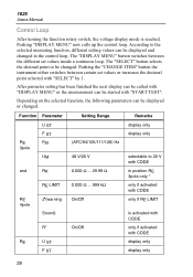
... control loop. Pushing the "CHANGE ITEM" button the instrument either switches between the different set values or increases the decimal point selected with "START TEST". 1625 Users Manual Control Loop After turning the function rotary switch, the voltage display mode is activated with CODE only if activated with CODE display only display only...
... control loop. Pushing the "CHANGE ITEM" button the instrument either switches between the different set values or increases the decimal point selected with "START TEST". 1625 Users Manual Control Loop After turning the function rotary switch, the voltage display mode is activated with CODE only if activated with CODE display only display only...


