Product Information Guide
Page 4
...and exiting paper. Epson printer stand model 8501 -A is properly aligned (no skewing to the fact that the paper exiting does not interfere with virtually all popular software. DFX-5000 4 12/12/88 9 - MATRIX PRINTER Installation/Support Tips Physical Installation The DFX-5000 printer is recommended but...paper supply shelf large enough to accommodate the printer, and its use is a very easy printer to set up, but due to either side) and that it will perform properly with the rear paper supply. Most software provides Epson FX printer support, but not required. DFX - 5000 DOT -
...and exiting paper. Epson printer stand model 8501 -A is properly aligned (no skewing to the fact that the paper exiting does not interfere with virtually all popular software. DFX-5000 4 12/12/88 9 - MATRIX PRINTER Installation/Support Tips Physical Installation The DFX-5000 printer is recommended but...paper supply shelf large enough to accommodate the printer, and its use is a very easy printer to set up, but due to either side) and that it will perform properly with the rear paper supply. Most software provides Epson FX printer support, but not required. DFX - 5000 DOT -
Service Manual
Page 9
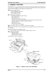
... and RS-232C serial interface standard Cl Epson ESC/P-83 (ESC/P version 83) printer driver (compatible with a maximum speed of 560 characters per second (ips) paper feeding - Automatic tear off - Exterior View of the printer are: Cl Maximum printing speeds: 560 ... continuous-sheet handling. The main features of the DFX-5000+ 1-1 Automatic interface selection - too cover "'"'"'"" 'NV' control panel poper separator ----,~"p=, >.G-np" u,...flta"n$ rf--f-lu- It is a 9-pin, serial, dot matrix printer with the FX-870/1170 and DFX-5000) D 9 character tables in the standard version...
... and RS-232C serial interface standard Cl Epson ESC/P-83 (ESC/P version 83) printer driver (compatible with a maximum speed of 560 characters per second (ips) paper feeding - Automatic tear off - Exterior View of the printer are: Cl Maximum printing speeds: 560 ... continuous-sheet handling. The main features of the DFX-5000+ 1-1 Automatic interface selection - too cover "'"'"'"" 'NV' control panel poper separator ----,~"p=, >.G-np" u,...flta"n$ rf--f-lu- It is a 9-pin, serial, dot matrix printer with the FX-870/1170 and DFX-5000) D 9 character tables in the standard version...
Service Manual
Page 40
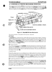
...acadents. LI Auto platen gap adjustment mechanism The printer mechanism has an automatic platen gap adjustment function that actually pMts characters (dot matrix patterns). When the printhead or fan is too hot, the printer stops printing until it includes an isolation resistance ... The printhead is less than 1 I@. DFx-5tW(h Sewka Manual Oparathg Prfncipka 2.1 OVERVIEW OF PRINTER MECHANISM OPERATION This section describes the Model 3C11 printer mechanism and explains how the printer works. Figure 2-1 shows the Model 3C11 printer mechanism. The CR motor drives the carriage...
...acadents. LI Auto platen gap adjustment mechanism The printer mechanism has an automatic platen gap adjustment function that actually pMts characters (dot matrix patterns). When the printhead or fan is too hot, the printer stops printing until it includes an isolation resistance ... The printhead is less than 1 I@. DFx-5tW(h Sewka Manual Oparathg Prfncipka 2.1 OVERVIEW OF PRINTER MECHANISM OPERATION This section describes the Model 3C11 printer mechanism and explains how the printer works. Figure 2-1 shows the Model 3C11 printer mechanism. The CR motor drives the carriage...

Service Manual
Page 52
...voltage. These switching regulator circuits perform voltage control and over-current limiting for approximately thee minutes after the printer is located under the carnage motor so that is a driver check to the motors. The Cl17 power supply board assembly includes a cooling km that it back ...+35 VDC creation circuits. (Ike +35 VDC line is supplied to six of the nine printhead pins (pins 1,3,5, 7,8, and 9); e m %i;' DFX-5000+ Sendee Mama! Therefore, after the power is too high). Before using a different AC power supply, replace the fuse and power cord. The AC voltage...
...voltage. These switching regulator circuits perform voltage control and over-current limiting for approximately thee minutes after the printer is located under the carnage motor so that is a driver check to the motors. The Cl17 power supply board assembly includes a cooling km that it back ...+35 VDC creation circuits. (Ike +35 VDC line is supplied to six of the nine printhead pins (pins 1,3,5, 7,8, and 9); e m %i;' DFX-5000+ Sendee Mama! Therefore, after the power is too high). Before using a different AC power supply, replace the fuse and power cord. The AC voltage...
Service Manual
Page 53
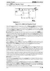
...comparators. If the output signal is HIGH from either comparator, the output signal is used to check the printhead drivers on and it cuts off . When the printer is used for 140 ms. The first rising voltage (+13 VDC) is turned on the +5 VDC line ...11 +12 +35VIX b +3CV,, UI'L.,., )-P PRIMERY CIRCUIT - If the printhead drivers are normal, the control board outputs the VPC signal to the C117 power supply board assembly. Pin 16 (+12) monitors the +5 VDC line. Operating Principles DFX-5000+ Service Manual 2.2.2 +5 VDC Line Regulator Circuit The +5 VDC line regulator circuit uses...
...comparators. If the output signal is HIGH from either comparator, the output signal is used to check the printhead drivers on and it cuts off . When the printer is used for 140 ms. The first rising voltage (+13 VDC) is turned on the +5 VDC line ...11 +12 +35VIX b +3CV,, UI'L.,., )-P PRIMERY CIRCUIT - If the printhead drivers are normal, the control board outputs the VPC signal to the C117 power supply board assembly. Pin 16 (+12) monitors the +5 VDC line. Operating Principles DFX-5000+ Service Manual 2.2.2 +5 VDC Line Regulator Circuit The +5 VDC line regulator circuit uses...
Service Manual
Page 58
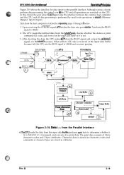
... CPU reads the latched data from the host computer is stored as character codes and commands or character types are executed via the CPU. AHribute T Printer Mechanism Driver o8 + Character Generator I Down Load ""; Rev. A 2-19 Yes -: + e Yes ')o BUSY or IACK L .......... Although various circuits perform data processing, the ... (IC7) provides the interface between the external heat computer and the CPU, and all operations are stored as attributes. DFX-5000+ Servics Mimml 0per8thg Ffinchl&e Figure 2-19 shows the data flow for data input via the MMIO accesses.
... CPU reads the latched data from the host computer is stored as character codes and commands or character types are executed via the CPU. AHribute T Printer Mechanism Driver o8 + Character Generator I Down Load ""; Rev. A 2-19 Yes -: + e Yes ')o BUSY or IACK L .......... Although various circuits perform data processing, the ... (IC7) provides the interface between the external heat computer and the CPU, and all operations are stored as attributes. DFX-5000+ Servics Mimml 0per8thg Ffinchl&e Figure 2-19 shows the data flow for data input via the MMIO accesses.
Service Manual
Page 66
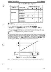
CR Motor Drive Sequence Operating Pdncipbs Carria#~T~;sfer Driving Mode Driver (Refer to thegatearray. 2. SFlet , . Rev. DFX-5000+ Service Manual Table 2-5. CR ports A, B, and C output the drive signal for the CR motor. Figure 2-24 shows the acceleration control curve. A 2-27...carriage speed moves to constant control speed smoothly to the PWM port of the gate array and determines the duty of the carriage. The printer can print while the carriage is labeled A and the driving modes are labeled B. Acceleration Control Cuwe In Figure 2-24, the acceleration curve ...
CR Motor Drive Sequence Operating Pdncipbs Carria#~T~;sfer Driving Mode Driver (Refer to thegatearray. 2. SFlet , . Rev. DFX-5000+ Service Manual Table 2-5. CR ports A, B, and C output the drive signal for the CR motor. Figure 2-24 shows the acceleration control curve. A 2-27...carriage speed moves to constant control speed smoothly to the PWM port of the gate array and determines the duty of the carriage. The printer can print while the carriage is labeled A and the driving modes are labeled B. Acceleration Control Cuwe In Figure 2-24, the acceleration curve ...
Service Manual
Page 67
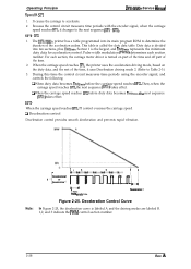
...driving mode 2. (Refer to determine the duration of the time. 2. Section 1 is called the duty data table. When the carriage speed reaches SP1, the printer uses the acceleration driving mode, based on 1 1 msec PWM parcdic time ; ;~,, ;;; : ! : : :::: : : Decalaratica 3 Figure 2-25.... driver is labeled A and the driving modes are labeled B. 1,2, and 3 indicate the PWM control section number. 2-28 Rev. Then, when the carnage speed reaches SP2, the next sequence (SP2-) takes effect. Operating Principle DFX-5000+ Service Manuai SpeeciO - SP1 1. SP1 - The DFX-5000+ printer ...
...driving mode 2. (Refer to determine the duration of the time. 2. Section 1 is called the duty data table. When the carriage speed reaches SP1, the printer uses the acceleration driving mode, based on 1 1 msec PWM parcdic time ; ;~,, ;;; : ! : : :::: : : Decalaratica 3 Figure 2-25.... driver is labeled A and the driving modes are labeled B. 1,2, and 3 indicate the PWM control section number. 2-28 Rev. Then, when the carnage speed reaches SP2, the next sequence (SP2-) takes effect. Operating Principle DFX-5000+ Service Manuai SpeeciO - SP1 1. SP1 - The DFX-5000+ printer ...
Service Manual
Page 79
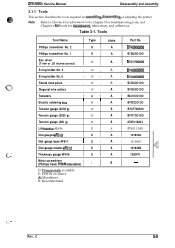
Table 3-1. Phillips screwdriver No. 2 0 A B743800200 Phillips screwdriver No. 1 0 A B7438OO1OO Box driver (7 mm or .28 inches across) o A B741700200 E-ring holder No. 3 E-ring holder No. 6 Round nose pliers Diagonal wire cutters...- O: Commeraally available E: EPSON exclusive A: Mandatory B: Recommended f..... ' Rev. Tools Tool Name Type class Part No. C 34 Note: Refer to Chapter 4 for adjustment tools, Chapter 5 for troubleshooting tools, and Chapter 6 for tools for assembling disassembling or adjusting the printer. DFX-5000+ Service Manual Disassembly and ...
Table 3-1. Phillips screwdriver No. 2 0 A B743800200 Phillips screwdriver No. 1 0 A B7438OO1OO Box driver (7 mm or .28 inches across) o A B741700200 E-ring holder No. 3 E-ring holder No. 6 Round nose pliers Diagonal wire cutters...- O: Commeraally available E: EPSON exclusive A: Mandatory B: Recommended f..... ' Rev. Tools Tool Name Type class Part No. C 34 Note: Refer to Chapter 4 for adjustment tools, Chapter 5 for troubleshooting tools, and Chapter 6 for tools for assembling disassembling or adjusting the printer. DFX-5000+ Service Manual Disassembly and ...
Service Manual
Page 138
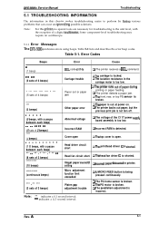
... printing or paper feeding. Q The printer backs out paper, but the previous print job is shorted. Head fan circuit short CIThe head fan driver IC is not tom off. t2The PG motor is detected. Rev. Some component-level troubleshooting may require an oscilloscope. 5.1.1 Error Messages The DFX-5000+ indicates errors using beeps. Illegal paper...
... printing or paper feeding. Q The printer backs out paper, but the previous print job is shorted. Head fan circuit short CIThe head fan driver IC is not tom off. t2The PG motor is detected. Rev. Some component-level troubleshooting may require an oscilloscope. 5.1.1 Error Messages The DFX-5000+ indicates errors using beeps. Illegal paper...
Service Manual
Page 150
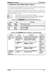
... in this column to isolate components in the power supply or on the main board and check the head driver voltage waveform. (Refer to Table 5-6.) Measure the voltage level of common printer problems. Use this section. Fuse F1 blows immediately after replacement. Then perform the proper repair. The line ... C1-C6 or RI is not being sent from the gate array on the main board. CLIMIT signal is present at CN3. DFX-5000+ Service Manual Troubleshooting 5.3 REPAIR OF THE POWER SUPPLY CIRCUIT This section provides detailed troubleshooting methods to isolate your problem.
... in this column to isolate components in the power supply or on the main board and check the head driver voltage waveform. (Refer to Table 5-6.) Measure the voltage level of common printer problems. Use this section. Fuse F1 blows immediately after replacement. Then perform the proper repair. The line ... C1-C6 or RI is not being sent from the gate array on the main board. CLIMIT signal is present at CN3. DFX-5000+ Service Manual Troubleshooting 5.3 REPAIR OF THE POWER SUPPLY CIRCUIT This section provides detailed troubleshooting methods to isolate your problem.
Service Manual
Page 154
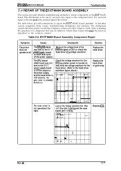
...HIGH level turns off the power supply). Replace the head driver or gate array. m ,92V d V24 ,80V SAVE Replace IC9. 4n- - ~ m f" * PE Rev. DFX-5000+ Service Manual Troubleshooting 5.4 REPAIR OF THE C117 MAIN ...BOARD ASSEMBLY This section provides detailed troubleshooting methods to the component level. It describes various symptoms, likely causes, troubleshooting checkpoints, and solutions. CI17 MAIN Board Assembly Component Repair Symptom The printer does not operate at CN1 or check the head driver...
...HIGH level turns off the power supply). Replace the head driver or gate array. m ,92V d V24 ,80V SAVE Replace IC9. 4n- - ~ m f" * PE Rev. DFX-5000+ Service Manual Troubleshooting 5.4 REPAIR OF THE C117 MAIN ...BOARD ASSEMBLY This section provides detailed troubleshooting methods to the component level. It describes various symptoms, likely causes, troubleshooting checkpoints, and solutions. CI17 MAIN Board Assembly Component Repair Symptom The printer does not operate at CN1 or check the head driver...
Service Manual
Page 162
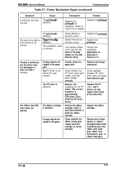
DFX-5000+ Service Manual Troubleshooting Table 5-7. Cause The printhead is defective. The Pfinthead is defective. Replace...Refer to Figure 5-4 for the PF motor. (The correct resistance is approximately 2.85 ohms.) Also check the PF motor drivers. The print is too light or print density is not driving the gear properly. Replace the printhead, Perform the parallelism...at the right and left sides of a dot wire is performed, but the printer does not feed paper or does not feed it feeds the ribbon normally. Replace the PF motor, and if drivers are lodged in the paper path. Replace ...
DFX-5000+ Service Manual Troubleshooting Table 5-7. Cause The printhead is defective. The Pfinthead is defective. Replace...Refer to Figure 5-4 for the PF motor. (The correct resistance is approximately 2.85 ohms.) Also check the PF motor drivers. The print is too light or print density is not driving the gear properly. Replace the printhead, Perform the parallelism...at the right and left sides of a dot wire is performed, but the printer does not feed paper or does not feed it feeds the ribbon normally. Replace the PF motor, and if drivers are lodged in the paper path. Replace ...


