
Users Guide
Page 19
...You can purchase online at epsonstore.com (U.S. Compatible HDMI cable Available for purchase from Epson or an authorized Epson reseller. Compatible DVI-D cable To sync additional BrightLink Pro projectors together, you need a stereo mini cable (commercially available) or the remote...wall mount (ELPMB46) Part number V13H010L92 V13H134A45 V12H777020 19 Available for purchase from Epson or an authorized Epson reseller. or 800-807-7766 in the U.S. Or you can purchase screens, other optional accessories, and replacement parts from certain ports VGA DVI-D Multiple BrightLink Pro...
...You can purchase online at epsonstore.com (U.S. Compatible HDMI cable Available for purchase from Epson or an authorized Epson reseller. Compatible DVI-D cable To sync additional BrightLink Pro projectors together, you need a stereo mini cable (commercially available) or the remote...wall mount (ELPMB46) Part number V13H010L92 V13H134A45 V12H777020 19 Available for purchase from Epson or an authorized Epson reseller. or 800-807-7766 in the U.S. Or you can purchase screens, other optional accessories, and replacement parts from certain ports VGA DVI-D Multiple BrightLink Pro...

Users Guide
Page 28
Projector Parts - Base 1 Ceiling mount holes (5) 2 Rear foot holes (2) 3 Security cable attachment point 4 Wall mounting plate holes (4) 5 Illumination sensor 6 Front foot hole Parent topic: Projector Part Locations 28
Projector Parts - Base 1 Ceiling mount holes (5) 2 Rear foot holes (2) 3 Security cable attachment point 4 Wall mounting plate holes (4) 5 Illumination sensor 6 Front foot hole Parent topic: Projector Part Locations 28

Users Guide
Page 30
Pen Stand 1 Front cover 2 Pen tip storage area 3 Pen storage area 4 Battery storage area 5 Wall mounting holes Parent topic: Projector Part Locations 30 Projector Parts -
Pen Stand 1 Front cover 2 Pen tip storage area 3 Pen storage area 4 Battery storage area 5 Wall mounting holes Parent topic: Projector Part Locations 30 Projector Parts -

Users Guide
Page 36
... outlet or extension cord. • If installing vertically on a table, the table projection mount (V12H516020) is required. • If installing on a wall, the wall mount (V12H777020) is required. • If the projector is not mounted, place it on a flat surface such as you select a projector location: • Follow...workspace. Setting Up the Projector Follow the instructions in these considerations in mind as a desk or table to be installed on a wall (with a wall mount) or vertically on a table (with your projector for ventilation, and do not place it on top of or next to ...
... outlet or extension cord. • If installing vertically on a table, the table projection mount (V12H516020) is required. • If installing on a wall, the wall mount (V12H777020) is required. • If the projector is not mounted, place it on a flat surface such as you select a projector location: • Follow...workspace. Setting Up the Projector Follow the instructions in these considerations in mind as a desk or table to be installed on a wall (with a wall mount) or vertically on a table (with your projector for ventilation, and do not place it on top of or next to ...

Users Guide
Page 352
...) and white brightness (white light output) will vary depending on usage conditions. white light output measured in accordance with ISO 21118. 16000:1 with IDMS 15.4; BrightLink Pro 1460Ui: Normal Power Consumption mode: White light output 4400 lumens (ISO 21118 standard) Color light output 4400 lumens ECO Power Consumption mode: White light output 2900... ratio Image size (in native aspect ratio) Projection distance (in native aspect ratio) Projection methods Optical aspect ratio (width-to 23.3 inches (0.59 m) Front, rear, wall-mounted, table-mounted, ceiling-mounted 16:10 352
...) and white brightness (white light output) will vary depending on usage conditions. white light output measured in accordance with ISO 21118. 16000:1 with IDMS 15.4; BrightLink Pro 1460Ui: Normal Power Consumption mode: White light output 4400 lumens (ISO 21118 standard) Color light output 4400 lumens ECO Power Consumption mode: White light output 2900... ratio Image size (in native aspect ratio) Projection distance (in native aspect ratio) Projection methods Optical aspect ratio (width-to 23.3 inches (0.59 m) Front, rear, wall-mounted, table-mounted, ceiling-mounted 16:10 352

Users Guide
Page 363
... soft surface, or set it on top of the projector so the bright light does not shine into the lens when the projector is mounted on a ceiling or wall, it should be installed by qualified technicians using the projector: • Do not look into your eyes. • Do not place your...of heat, high-voltage electrical wires, or sources of magnetic fields. • Use the type of this projector. • When installing or adjusting a ceiling or wall mount, do not use oils or lubricants. Do not tilt the projector more than 3° forward or back. • If the projector is on the projector...
... soft surface, or set it on top of the projector so the bright light does not shine into the lens when the projector is mounted on a ceiling or wall, it should be installed by qualified technicians using the projector: • Do not look into your eyes. • Do not place your...of heat, high-voltage electrical wires, or sources of magnetic fields. • Use the type of this projector. • When installing or adjusting a ceiling or wall mount, do not use oils or lubricants. Do not tilt the projector more than 3° forward or back. • If the projector is on the projector...
Installation Guide - Control Pad and Touch Unit
Page 3
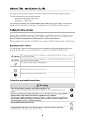
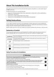
...injury or property damage. Safety Instructions For your Epson® projector. Make sure you mount the projector on a concrete wall. Confirm the weight of Symbols The warning marks shown below are covered by this guide to hold the projector, the wall mount, as well as the Control Pad and .../697Ui • BrightLink Pro 1450Ui/1460Ui The Control Pad is not installed and operated properly, the light emitted from the laser could result in personal injury or even death due to any screws or bolts. If the Touch Unit is included with the wall mount, the wall must not be done...
...injury or property damage. Safety Instructions For your Epson® projector. Make sure you mount the projector on a concrete wall. Confirm the weight of Symbols The warning marks shown below are covered by this guide to hold the projector, the wall mount, as well as the Control Pad and .../697Ui • BrightLink Pro 1450Ui/1460Ui The Control Pad is not installed and operated properly, the light emitted from the laser could result in personal injury or even death due to any screws or bolts. If the Touch Unit is included with the wall mount, the wall must not be done...
Installation Guide - Ultra-Short Throw Wall Mount ELPMB46
Page 2
... could cause personal injury or property damage. Observe the following projectors are used throughout this guide before using the Epson® ELPMB46 wall mount. Symbol indicating an action that must not be done Symbol indicating an action that , if ignored, could possibly...power cord carefully. The installation work (wall mounting) should be performed by this guide: • BrightLink® 475Wi/480i/485Wi/575Wi/575Wi+/585Wi/585Wi+/595Wi/595Wi+/675Wi+/685Wi/685Wi+/ 695Wi/695Wi+/696Ui/697Ui • BrightLink Pro 1410Wi/1420Wi/1430Wi/1450Ui/1460Ui • PowerLite® 470/475W...
... could cause personal injury or property damage. Observe the following projectors are used throughout this guide before using the Epson® ELPMB46 wall mount. Symbol indicating an action that must not be done Symbol indicating an action that , if ignored, could possibly...power cord carefully. The installation work (wall mounting) should be performed by this guide: • BrightLink® 475Wi/480i/485Wi/575Wi/575Wi+/585Wi/585Wi+/595Wi/595Wi+/675Wi+/685Wi/685Wi+/ 695Wi/695Wi+/696Ui/697Ui • BrightLink Pro 1410Wi/1420Wi/1430Wi/1450Ui/1460Ui • PowerLite® 470/475W...
Installation Guide - Ultra-Short Throw Wall Mount ELPMB46
Page 3
... or property damage. Install the wall mount so that the screws have not become loose on the wall mount. Nuts and bolts smaller than M10 could also cause the wall mount or projector to install or adjust the wall mount. This wall mount should be exceeded. It could cause the wall mount to the projector or mounting surface. Epson accepts no broken parts or...
... or property damage. Install the wall mount so that the screws have not become loose on the wall mount. Nuts and bolts smaller than M10 could also cause the wall mount or projector to install or adjust the wall mount. This wall mount should be exceeded. It could cause the wall mount to the projector or mounting surface. Epson accepts no broken parts or...

Installation Guide - Ultra-Short Throw Wall Mount ELPMB46
Page 5
...13 Installation worksheet for projecting on a pre-installed wall-mounted board 14 Installation worksheet for projecting on a plain wall 15 Projection distance worksheets 16 Diagonal image size and mounting position 17 Distance from projection surface to wall plate 18 Installation measurement tables 18 Measurements in ...25 Assemble the parts 25 Install the wall plate on the wall 27 Determine the projection distance and pull out the mount arm slider 29 Route the cables through the wall mount arm 30 Attach the mount arm to the wall plate 30 Adjust the vertical slide position...
...13 Installation worksheet for projecting on a pre-installed wall-mounted board 14 Installation worksheet for projecting on a plain wall 15 Projection distance worksheets 16 Diagonal image size and mounting position 17 Distance from projection surface to wall plate 18 Installation measurement tables 18 Measurements in ...25 Assemble the parts 25 Install the wall plate on the wall 27 Determine the projection distance and pull out the mount arm slider 29 Route the cables through the wall mount arm 30 Attach the mount arm to the wall plate 30 Adjust the vertical slide position...
Installation Guide - Ultra-Short Throw Wall Mount ELPMB46
Page 7
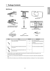
... commercially available M10 × 60 mm anchors (at least 3) to attach the wall plate to install it as directed in this guide. English 1 Package Contents Wall Mount Wall mount Wall plate Wall plate cover 3-axis adjustment unit and slide plate (attached when shipped) Hexagonal shaft ... washer/spring washer Quantity 5 4 4 Application For wall plate assembly For 3-axis adjustment unit/wall mount installation For slide plate/projector installation M6 × 20 mm hexagon shoulder bolt with washer/ spring washer 1 For wall mount/wall plate installation M6 × 20 mm cross recessed ...
... commercially available M10 × 60 mm anchors (at least 3) to attach the wall plate to install it as directed in this guide. English 1 Package Contents Wall Mount Wall mount Wall plate Wall plate cover 3-axis adjustment unit and slide plate (attached when shipped) Hexagonal shaft ... washer/spring washer Quantity 5 4 4 Application For wall plate assembly For 3-axis adjustment unit/wall mount installation For slide plate/projector installation M6 × 20 mm hexagon shoulder bolt with washer/ spring washer 1 For wall mount/wall plate installation M6 × 20 mm cross recessed ...
Installation Guide - Ultra-Short Throw Wall Mount ELPMB46
Page 8
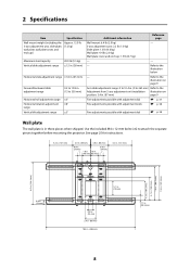
...176; range Vertical tilt adjustment range ±3° Additional information Reference page Wall mount: 6.4 lb (2.9 kg) - 3-axis adjustment unit: 2.2 lb (1.0 kg) Slide plate: 1.3 lb (0.6 kg) Wall plate: 4.4 lb (2.0 kg) Wall plate cover and end cap: 1.5 lb (0.7 kg) - - - Use...the included M4 × 12 mm bolts (×6) to the illustration below - 2 Specifications Item Specification Wall mount weight (including the 3-axis adjustment unit, slide plate, wall plate, wall plate cover, and end cap) Approx. 15.9 lb (7.2 kg) Maximum load capacity Vertical slide adjustment range...
...176; range Vertical tilt adjustment range ±3° Additional information Reference page Wall mount: 6.4 lb (2.9 kg) - 3-axis adjustment unit: 2.2 lb (1.0 kg) Slide plate: 1.3 lb (0.6 kg) Wall plate: 4.4 lb (2.0 kg) Wall plate cover and end cap: 1.5 lb (0.7 kg) - - - Use...the included M4 × 12 mm bolts (×6) to the illustration below - 2 Specifications Item Specification Wall mount weight (including the 3-axis adjustment unit, slide plate, wall plate, wall plate cover, and end cap) Approx. 15.9 lb (7.2 kg) Maximum load capacity Vertical slide adjustment range...
Installation Guide - Ultra-Short Throw Wall Mount ELPMB46
Page 11
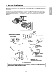
... (not included) Touch Unit connection cable LAN device Audio cable (not included) Computer cable (for computer video output) Microphone Computer Document camera (Epson DC-07) USB cable (for your projector. Make sure you also have the power cord, computer cable, and other devices, such as a...the model in toolbar, you have all necessary cables for the Touch Unit (if applicable) and other parts at the location where the wall mount is to the online User's Guide for Easy Interactive Function) Dedicated USB cable (supplied with document camera) For Interactive Use When interacting ...
... (not included) Touch Unit connection cable LAN device Audio cable (not included) Computer cable (for computer video output) Microphone Computer Document camera (Epson DC-07) USB cable (for your projector. Make sure you also have the power cord, computer cable, and other devices, such as a...the model in toolbar, you have all necessary cables for the Touch Unit (if applicable) and other parts at the location where the wall mount is to the online User's Guide for Easy Interactive Function) Dedicated USB cable (supplied with document camera) For Interactive Use When interacting ...
Installation Guide - Ultra-Short Throw Wall Mount ELPMB46
Page 13
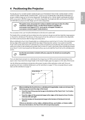
... included wall mount determines the maximum image size and how high the image appears on page 15. If you must install the Touch Unit on a plain wall, use the included Touch Unit Bracket. If you are projecting on the whiteboard or screen. If you are planning to 100 inches diagonally. The BrightLink Pro 1450Ui/1460Ui and BrightLink... the Touch Unit: 1 to 4 inches (25 to 100 mm) ❏ From the edges of the projected image to the edges of the board: at www.epson.com/support (U.S.), www.epson.ca/support (Canada), or www.epson.com/jm/support (Latin America).
... included wall mount determines the maximum image size and how high the image appears on page 15. If you must install the Touch Unit on a plain wall, use the included Touch Unit Bracket. If you are projecting on the whiteboard or screen. If you are planning to 100 inches diagonally. The BrightLink Pro 1450Ui/1460Ui and BrightLink... the Touch Unit: 1 to 4 inches (25 to 100 mm) ❏ From the edges of the projected image to the edges of the board: at www.epson.com/support (U.S.), www.epson.ca/support (Canada), or www.epson.com/jm/support (Latin America).
Installation Guide - Ultra-Short Throw Wall Mount ELPMB46
Page 14
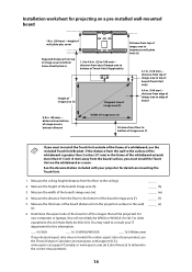
... board (distance from edge of image area to edge of a whiteboard, use the Throw Distance Calculator at www.epson.com/support (U.S.), www.epson.ca/support (Canada), or www.epson.com.jm (Latin America) to determine the correct measurements. 14 For older equipment, this will most likely be ...does not match the native aspect ratio of your projector for projecting on a pre-installed wall-mounted board 10 in. (254 mm)-height of wall plate plus cover Required distance from the floor to the wall) _____ (x) (x). 6. Measure the distance from top of image area to bottom holes of...
... board (distance from edge of image area to edge of a whiteboard, use the Throw Distance Calculator at www.epson.com/support (U.S.), www.epson.ca/support (Canada), or www.epson.com.jm (Latin America) to determine the correct measurements. 14 For older equipment, this will most likely be ...does not match the native aspect ratio of your projector for projecting on a pre-installed wall-mounted board 10 in. (254 mm)-height of wall plate plus cover Required distance from the floor to the wall) _____ (x) (x). 6. Measure the distance from top of image area to bottom holes of...
Installation Guide - Ultra-Short Throw Wall Mount ELPMB46
Page 18
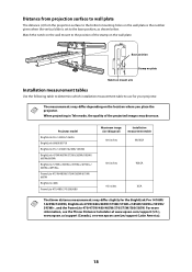
Projector model BrightLink Pro 1450Ui/1460Ui BrightLink 696Ui/697Ui BrightLink Pro 1410Wi/1420Wi/1430Wi BrightLink 475W/485W/575Wi/585Wi/595Wi/ 685Wi/695Wi BrightLink 575Wi+/585Wi+/595Wi+/675Wi+/ 685Wi+/695Wi+ PowerLite 475W/485W/575W/585W/675W/ 685W BrightLink 480i PowerLite 470/480/570/580/680 Maximum image size (diagonal... from projection surface to wall plate The distance (c) from the projection surface to the bottom mounting holes on the wall plate is the number given when the vertical slide is set to use for the BrightLink Pro 1410Wi/ 1420Wi/1430Wi, BrightLink 475W/480i/485W/575Wi/...
Projector model BrightLink Pro 1450Ui/1460Ui BrightLink 696Ui/697Ui BrightLink Pro 1410Wi/1420Wi/1430Wi BrightLink 475W/485W/575Wi/585Wi/595Wi/ 685Wi/695Wi BrightLink 575Wi+/585Wi+/595Wi+/675Wi+/ 685Wi+/695Wi+ PowerLite 475W/485W/575W/585W/675W/ 685W BrightLink 480i PowerLite 470/480/570/580/680 Maximum image size (diagonal... from projection surface to wall plate The distance (c) from the projection surface to the bottom mounting holes on the wall plate is the number given when the vertical slide is set to use for the BrightLink Pro 1410Wi/ 1420Wi/1430Wi, BrightLink 475W/480i/485W/575Wi/...
Installation Guide - Ultra-Short Throw Wall Mount ELPMB46
Page 25
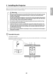
... or inadequate installation. Nuts and bolts smaller than M10 could fall . ❏ Epson accepts no responsibility for your wall type. Assemble the wall plate. Warning ❏ When you ignore these steps, the wall mount could cause the wall mount to hold the projector and the wall mount, as well as the Control Pad and the Touch Unit, if applicable...
... or inadequate installation. Nuts and bolts smaller than M10 could fall . ❏ Epson accepts no responsibility for your wall type. Assemble the wall plate. Warning ❏ When you ignore these steps, the wall mount could cause the wall mount to hold the projector and the wall mount, as well as the Control Pad and the Touch Unit, if applicable...
Installation Guide - Ultra-Short Throw Wall Mount ELPMB46
Page 29
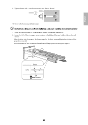
C Determine the projection distance and pull out the mount arm slider 1. Loosen the M4 × 12 mm hexagon socket head cap bolts (×2), and then pull out the slider on pages 19 to measure ... with the measure (b+x) that is equal to the wall. 10. Align the slider with a wrench to secure the wall plate to the slider measure (b) plus the thickness of how to 24, check the number for the slider measure (b). 2. Using the tables on the wall mount. Remove the temporary wall plate screw. Slider measure 29 English 9.
C Determine the projection distance and pull out the mount arm slider 1. Loosen the M4 × 12 mm hexagon socket head cap bolts (×2), and then pull out the slider on pages 19 to measure ... with the measure (b+x) that is equal to the wall. 10. Align the slider with a wrench to secure the wall plate to the slider measure (b) plus the thickness of how to 24, check the number for the slider measure (b). 2. Using the tables on the wall mount. Remove the temporary wall plate screw. Slider measure 29 English 9.
Installation Guide - Ultra-Short Throw Wall Mount ELPMB46
Page 30
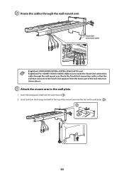
... D Route the cables through the wall mount arm. Insert and turn the hexagonal shaft at the top of the wall mount as shown above. E Attach the mount arm to route the Touch Unit connection cable through the wall mount arm Touch Unit connection cable BrightLink 595Wi/695Wi/595Wi+/695Wi+/696Ui/697Ui and BrightLink Pro 1430Wi/1450Ui/1460Ui: Make sure to the...
... D Route the cables through the wall mount arm. Insert and turn the hexagonal shaft at the top of the wall mount as shown above. E Attach the mount arm to route the Touch Unit connection cable through the wall mount arm Touch Unit connection cable BrightLink 595Wi/695Wi/595Wi+/695Wi+/696Ui/697Ui and BrightLink Pro 1430Wi/1450Ui/1460Ui: Make sure to the...

Installation Guide - Ultra-Short Throw Wall Mount ELPMB46
Page 32
Adjust the vertical slide with the alignment mark on the arm with the M8 hexagon bolt at the bottom of the wall mount ( ), or the hexagonal shaft at the top of the arm 1. Tightening the hexagonal shaft raises the wall mount, and loosening the shaft lowers it ( ). Start by aligning the notch on the wall plate as shown below. Alignment marks 2. Tighten the M6 × 20 mm hexagon shoulder bolt to secure the wall mount. 32 Tightening the M8 hexagon bolt lowers the wall mount, and loosening the bolt raises it ( ). F Adjust the vertical slide position of the wall mount ( ).
Adjust the vertical slide with the alignment mark on the arm with the M8 hexagon bolt at the bottom of the wall mount ( ), or the hexagonal shaft at the top of the arm 1. Tightening the hexagonal shaft raises the wall mount, and loosening the shaft lowers it ( ). Start by aligning the notch on the wall plate as shown below. Alignment marks 2. Tighten the M6 × 20 mm hexagon shoulder bolt to secure the wall mount. 32 Tightening the M8 hexagon bolt lowers the wall mount, and loosening the bolt raises it ( ). F Adjust the vertical slide position of the wall mount ( ).


