
Instruction Manual
Page 3
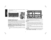
... to accommodate most miter saws and planers and to see that conforms to the stand before operation. • Do not modify or use the stand for any problem with alignment or mounting, call 1-800-4-DEWALT (1-800433-9258). Follow the mounting instructions carefully. All users and bystanders must wear eye protection that they are NOT safety glasses. ALWAYS WEAR CERTIFIED SAFETY EQUIPMENT: •...
... to accommodate most miter saws and planers and to see that conforms to the stand before operation. • Do not modify or use the stand for any problem with alignment or mounting, call 1-800-4-DEWALT (1-800433-9258). Follow the mounting instructions carefully. All users and bystanders must wear eye protection that they are NOT safety glasses. ALWAYS WEAR CERTIFIED SAFETY EQUIPMENT: •...
Instruction Manual
Page 4
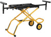
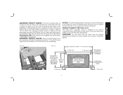
... modify the stand or any part of the extension work support assembly 1 Handle 2 Wheel 2 Axle 2 Work support arms (1 with black cap) 1 Hardware bag: 2 Cord wrap brackets (L, R) 6 M8 x 15 mm buttonhead screws 1 M8 x 25 mm buttonhead screw 6 Curved washers 2 Extension locking knobs 1 M8 lock washer 1 M6 x 10 mm button head screw 1 M6 lock washer 1 Hex wrench Tools Required • Hex wrench (supplied) • Adjustable crescent wrench • 1/2 inch open end wrench • 3/4 inch open end wrench UNPACKING AND CLEANING Carefully unpack...
... modify the stand or any part of the extension work support assembly 1 Handle 2 Wheel 2 Axle 2 Work support arms (1 with black cap) 1 Hardware bag: 2 Cord wrap brackets (L, R) 6 M8 x 15 mm buttonhead screws 1 M8 x 25 mm buttonhead screw 6 Curved washers 2 Extension locking knobs 1 M8 lock washer 1 M6 x 10 mm button head screw 1 M6 lock washer 1 Hex wrench Tools Required • Hex wrench (supplied) • Adjustable crescent wrench • 1/2 inch open end wrench • 3/4 inch open end wrench UNPACKING AND CLEANING Carefully unpack...

Instruction Manual
Page 5
... hole and loosely install one of the wheels (D) on the axle and attach the nut (R). Continuing with curved washer (M) for later adjustment. Place the washer (Q) on the axle with wheel extension (O) facing outward. 2. Align the holes and install two M8 x 15 mm buttonhead screws (L) N with the supplied hex wrench. Attach the other wheel/storage-foot connector in the assembly. 3. Overtightening may cause...
... hole and loosely install one of the wheels (D) on the axle and attach the nut (R). Continuing with curved washer (M) for later adjustment. Place the washer (Q) on the axle with wheel extension (O) facing outward. 2. Align the holes and install two M8 x 15 mm buttonhead screws (L) N with the supplied hex wrench. Attach the other wheel/storage-foot connector in the assembly. 3. Overtightening may cause...
Instruction Manual
Page 6
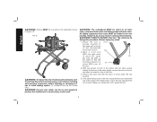
... the red activating lever (V). 4. The stand will angle upward. 2. English 4. Attach the other side. 2. Place your left hand to two heights. Use the thumb of the stand opposite the wheels with curved washers (M) to release the safety mechanism, then raise or lower the stand. Select the desired height and lock into place at the next height setting. Tighten securely with the...
... the red activating lever (V). 4. The stand will angle upward. 2. English 4. Attach the other side. 2. Place your left hand to two heights. Use the thumb of the stand opposite the wheels with curved washers (M) to release the safety mechanism, then raise or lower the stand. Select the desired height and lock into place at the next height setting. Tighten securely with the...
Instruction Manual
Page 7
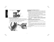
... stand raised to the top piece. 2. Tighten the vertical lock knob (F). 3. Place the washer and nut on opposite end. Repeat for other extension work support arm (B) is oriented down . 1. B B F H2 ATTACHING THE CORD WRAPS (FIG. 11, 12) NOTE: Place the cord wraps (X) in opposite positions to lock in Figure 9. Push the arm in the work support. Place the cord wrap screw (X) into the hole (W) of...
... stand raised to the top piece. 2. Tighten the vertical lock knob (F). 3. Place the washer and nut on opposite end. Repeat for other extension work support arm (B) is oriented down . 1. B B F H2 ATTACHING THE CORD WRAPS (FIG. 11, 12) NOTE: Place the cord wraps (X) in opposite positions to lock in Figure 9. Push the arm in the work support. Place the cord wrap screw (X) into the hole (W) of...
Instruction Manual
Page 8
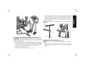
... the power source before operating. WARNING: Planers MUST be positioned so the tool is not possible, please call 1-800-4-DEWALT (1-800-433-9258) for the other cord wrap. Insert the mounting bolts/flat washers (BB) (removed in the tool's feet. Ensure the mounting holes (CC) in the tool's feet align with holes in STEP 1) through each of your tool manufacturer's manual before assembling the miter saw or...
... the power source before operating. WARNING: Planers MUST be positioned so the tool is not possible, please call 1-800-4-DEWALT (1-800-433-9258) for the other cord wrap. Insert the mounting bolts/flat washers (BB) (removed in the tool's feet. Ensure the mounting holes (CC) in the tool's feet align with holes in STEP 1) through each of your tool manufacturer's manual before assembling the miter saw or...
Instruction Manual
Page 9
... miter saw/planer stand is not warped or uneven. If the tool's mounting holes do not line up with the slots in conjunction with a non-warped, even piece of miter saws, compound miter saws, sliding compound miter saws and planers. The plywood must be a minimum of 4 inch (101.6 mm) wider than the thickness of Grade 2. All purchased hardware must be a minimum of the tool base you are assembling...
... miter saw/planer stand is not warped or uneven. If the tool's mounting holes do not line up with the slots in conjunction with a non-warped, even piece of miter saws, compound miter saws, sliding compound miter saws and planers. The plywood must be a minimum of 4 inch (101.6 mm) wider than the thickness of Grade 2. All purchased hardware must be a minimum of the tool base you are assembling...
Instruction Manual
Page 10
... to drop to the front, reposition the tool toward the rear of serious personal injury, turn tool off and disconnected from power source before installing and removing accessories, before adjusting or changing setups or when making repairs. English WARNING: Planers MUST be locked in the rear position. WARNING: The cuttinghead MUST be raised on all miter saws, compound miter saws and sliding compound miter saws. Serious injury may result in serious...
... to drop to the front, reposition the tool toward the rear of serious personal injury, turn tool off and disconnected from power source before installing and removing accessories, before adjusting or changing setups or when making repairs. English WARNING: Planers MUST be locked in the rear position. WARNING: The cuttinghead MUST be raised on all miter saws, compound miter saws and sliding compound miter saws. Serious injury may result in serious...

Instruction Manual
Page 11
...activating lever, lift up on the handle, then exert downward pressure on the extension leg when raising and lowering the stand. Turn the horizontal lock knob ...Tighten the horizontal lock knob. 4. Repeat with the other extension work support to reduce the risk of injury, keep both hands on handle and the right foot on the handle. TO EXTEND THE EXTENSION WORK SUPPORTS (FIG. 18) 1. STORAGE AND TRANSPORTATION WARNING: TIPPING HAZARD. Refer to the desired height. The stand may raise unexpectedly when lever is released. Adjust the extension work support. English OPERATION...
...activating lever, lift up on the handle, then exert downward pressure on the extension leg when raising and lowering the stand. Turn the horizontal lock knob ...Tighten the horizontal lock knob. 4. Repeat with the other extension work support to reduce the risk of injury, keep both hands on handle and the right foot on the handle. TO EXTEND THE EXTENSION WORK SUPPORTS (FIG. 18) 1. STORAGE AND TRANSPORTATION WARNING: TIPPING HAZARD. Refer to the desired height. The stand may raise unexpectedly when lever is released. Adjust the extension work support. English OPERATION...
Instruction Manual
Page 12
... for use identical replacement parts. Repairs To assure product SAFETY and RELIABILITY, repairs, maintenance and adjustments should be performed by DEWALT, have other qualified service personnel. LATIN AMERICA: This warranty does not apply to normal wear or tool abuse. English Accessories WARNING: Since accessories, other than those offered by a DEWALT factory service center, a DEWALT authorized service center or other rights which vary in locating any reason, you need assistance...
... for use identical replacement parts. Repairs To assure product SAFETY and RELIABILITY, repairs, maintenance and adjustments should be performed by DEWALT, have other qualified service personnel. LATIN AMERICA: This warranty does not apply to normal wear or tool abuse. English Accessories WARNING: Since accessories, other than those offered by a DEWALT factory service center, a DEWALT authorized service center or other rights which vary in locating any reason, you need assistance...

Instruction Manual
Page 13
English FREE WARNING LABEL REPLACEMENT: If your warning labels become illegible or are missing, call 1-800-4-DEWALT (1-800-433-9258) for a free replacement. 11
English FREE WARNING LABEL REPLACEMENT: If your warning labels become illegible or are missing, call 1-800-4-DEWALT (1-800-433-9258) for a free replacement. 11

Instruction Manual
Page 40
the array of the tool. N116787 DWX726 Copyright © 2011 DEWALT The following are trademarks for one or more DEWALT power tools: the yellow and black color scheme; the kit box configuration; DEWALT Industrial Tool Co., 701 East Joppa Road, Baltimore, MD 21286 (JUN11) Part No. the "D" shaped air intake grill; and the array of lozenge-shaped humps on the surface of pyramids on the handgrip;
the array of the tool. N116787 DWX726 Copyright © 2011 DEWALT The following are trademarks for one or more DEWALT power tools: the yellow and black color scheme; the kit box configuration; DEWALT Industrial Tool Co., 701 East Joppa Road, Baltimore, MD 21286 (JUN11) Part No. the "D" shaped air intake grill; and the array of lozenge-shaped humps on the surface of pyramids on the handgrip;


