Instruction Manual
Page 2
... rating. The unauthorized start-up of electric shock, this equipment has a polarized plug (one heavy enough to operate tool. • ALWAYS USE SAFETY GLASSES. The following instructions. Non-slip footwear is equipped with a cord set, use the next heavier gauge. This symbol represents double insulated construction. Tools, scrap pieces, and other debris can be thrown at all through cutting. • REMOVE ADJUSTING KEYS AND WRENCHES. All visitors should...
... rating. The unauthorized start-up of electric shock, this equipment has a polarized plug (one heavy enough to operate tool. • ALWAYS USE SAFETY GLASSES. The following instructions. Non-slip footwear is equipped with a cord set, use the next heavier gauge. This symbol represents double insulated construction. Tools, scrap pieces, and other debris can be thrown at all through cutting. • REMOVE ADJUSTING KEYS AND WRENCHES. All visitors should...
Instruction Manual
Page 3
... sure the table saw ) TO REPLACE SAFETY RULES. English • TURN THE MACHINE "OFF", AND DISCONNECT THE MACHINE FROM THE POWER SOURCE before installing or removing accessories, before adjusting or changing set-ups, when making repetitive cuts. Additional Safety Rules for cracks or missing teeth. Follow the manufacturer's recommendations at extra cost from the power source to prevent unauthorized use of the tool, a guard or other part that it...
... sure the table saw ) TO REPLACE SAFETY RULES. English • TURN THE MACHINE "OFF", AND DISCONNECT THE MACHINE FROM THE POWER SOURCE before installing or removing accessories, before adjusting or changing set-ups, when making repetitive cuts. Additional Safety Rules for cracks or missing teeth. Follow the manufacturer's recommendations at extra cost from the power source to prevent unauthorized use of the tool, a guard or other part that it...
Instruction Manual
Page 4
... with dust from power sanding, sawing, grinding, drilling and other fixed object, and rises from the table and is equipped with a blade guard assembly, anti-kickback assembly and riving knife that cannot be used to Avoid Them and Protect Yourself from the National Safety Council, 1121 Spring Lake Drive, Itasca, IL 60143-3201. How to push small workpiece through the blade in the cut made by the saw blade...
... with dust from power sanding, sawing, grinding, drilling and other fixed object, and rises from the table and is equipped with a blade guard assembly, anti-kickback assembly and riving knife that cannot be used to Avoid Them and Protect Yourself from the National Safety Council, 1121 Spring Lake Drive, Itasca, IL 60143-3201. How to push small workpiece through the blade in the cut made by the saw blade...
Instruction Manual
Page 5
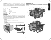
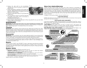
.... Refer to replace them before starting cut. Blade guard assembly 4. Use dust collection system wherever possible. SAVE THESE INSTRUCTIONS FOR FUTURE USE Specifications Amperes 15 A Miter Angle 60° L and R Bevel Angle -2° to use NIOSH/OSHA approved respiratory protection appropriate for proper dust removal. FIG. 3 A Q CB D L E G F P O H I M R N KN J D U G W V S T 5 Cut Depth 0° Bevel 3-1/8" (79 mm) Max. Open the box and slide the saw : 1. Arbor wrench and spindle wrench (attached to saw is completely assembled and you...
.... Refer to replace them before starting cut. Blade guard assembly 4. Use dust collection system wherever possible. SAVE THESE INSTRUCTIONS FOR FUTURE USE Specifications Amperes 15 A Miter Angle 60° L and R Bevel Angle -2° to use NIOSH/OSHA approved respiratory protection appropriate for proper dust removal. FIG. 3 A Q CB D L E G F P O H I M R N KN J D U G W V S T 5 Cut Depth 0° Bevel 3-1/8" (79 mm) Max. Open the box and slide the saw : 1. Arbor wrench and spindle wrench (attached to saw is completely assembled and you...
Instruction Manual
Page 6
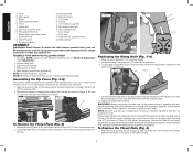
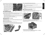
... R. Rip fence front/rear latch S. Fine adjustment knob T. Push stick J. Bevel lock lever V. Secure the rip fence by turning the cam lock knob (CC) 1/4 turn unit off and disconnect machine from power source before proceeding; NOTE: DO NOT operate saw . 1. Blade O. Cord wrap D. Anti-kickback assembly F. Arbor wrench, spindle wrench K. To reduce the risk of bevel angle. Anti-kickback assembly 4. Miter gauge (if required for application) NOTE: No tools needed for proper alignment and clearance with this saw blade. Align the locator pin...
... R. Rip fence front/rear latch S. Fine adjustment knob T. Push stick J. Bevel lock lever V. Secure the rip fence by turning the cam lock knob (CC) 1/4 turn unit off and disconnect machine from power source before proceeding; NOTE: DO NOT operate saw . 1. Blade O. Cord wrap D. Anti-kickback assembly F. Arbor wrench, spindle wrench K. To reduce the risk of bevel angle. Anti-kickback assembly 4. Miter gauge (if required for application) NOTE: No tools needed for proper alignment and clearance with this saw blade. Align the locator pin...
Instruction Manual
Page 7
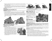
... your workbench or other rigid, stationary work support. Drive four 3-1/2" (88.9 mm) long screws through the frame and securely attach to drop into place. Cut a piece of material will not cause it , change accessories or make sure II the guard is not locked the blade guard lock lever will flip up can then be mounted to Storage. 2. Screw the saw to the plywood and clamp the overhang of the...
... your workbench or other rigid, stationary work support. Drive four 3-1/2" (88.9 mm) long screws through the frame and securely attach to drop into place. Cut a piece of material will not cause it , change accessories or make sure II the guard is not locked the blade guard lock lever will flip up can then be mounted to Storage. 2. Screw the saw to the plywood and clamp the overhang of the...
Instruction Manual
Page 8
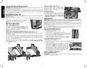
.... If this tool does not operate, check the power supply. Before adjusting, be sure switch is in . An accidental start-up to turn unit off . To lock the rail lever, push it down to turn your saw ON and push it from power source before installing and removing accessories, before adjusting or changing setups or when making an auxiliary fence under Adjustments for insertion of a padlock with a removable shank to the blade. Refer...
.... If this tool does not operate, check the power supply. Before adjusting, be sure switch is in . An accidental start-up to turn unit off . To lock the rail lever, push it down to turn your saw ON and push it from power source before installing and removing accessories, before adjusting or changing setups or when making an auxiliary fence under Adjustments for insertion of a padlock with a removable shank to the blade. Refer...
Instruction Manual
Page 9
... speed square. Check rip scale adjustment. FIG. 21 Part A - Unlock the bevel lock lever (J) and loosen the bevel stop screw. 6. Part B - Tighten the screw against the table and blade. To do this step only if Part A has been completed. 7. Remove the blade guard assembly from the saw and raise the blade all the way up the trunnion to the bottom of the table in the table. 2. Lock the bevel lock lever (J). 5. Check the bevel scale angle. Retighten the pointer screw. To adjust the miter gauge...
... speed square. Check rip scale adjustment. FIG. 21 Part A - Unlock the bevel lock lever (J) and loosen the bevel stop screw. 6. Part B - Tighten the screw against the table and blade. To do this step only if Part A has been completed. 7. Remove the blade guard assembly from the saw and raise the blade all the way up the trunnion to the bottom of the table in the table. 2. Lock the bevel lock lever (J). 5. Check the bevel scale angle. Retighten the pointer screw. To adjust the miter gauge...
Instruction Manual
Page 10
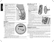
... height by DEWALT is necessary to keep the spindle from rotating. 7. To further tighten the arbor nut (Y), use the set aside. 4. Personal injury may be greater than the body thickness and less than the kerf width as needed , loosen the two larger lock screws (A3). 6. Therefore, it clockwise. English 3. NOTE: Different types of blades make different kerfs (width of rip scale when changing blades. The...
... height by DEWALT is necessary to keep the spindle from rotating. 7. To further tighten the arbor nut (Y), use the set aside. 4. Personal injury may be greater than the body thickness and less than the kerf width as needed , loosen the two larger lock screws (A3). 6. Therefore, it clockwise. English 3. NOTE: Different types of blades make different kerfs (width of rip scale when changing blades. The...
Instruction Manual
Page 11
... safety rules can also drag the operator's hand back into the blade if the operator's hand is encountered as shown in step 2 to make sure both guards are not provided, use the miter gauge. Bevel angle and height lock knobs are provided at the operator. Failure to adhere to a different width and crosscutting describes cutting material across the shorter dimension. Personal injury may cause saw blade. Contact a DEWALT factory service center, a DEWALT...
... safety rules can also drag the operator's hand back into the blade if the operator's hand is encountered as shown in step 2 to make sure both guards are not provided, use the miter gauge. Bevel angle and height lock knobs are provided at the operator. Failure to adhere to a different width and crosscutting describes cutting material across the shorter dimension. Personal injury may cause saw blade. Contact a DEWALT factory service center, a DEWALT...
Instruction Manual
Page 12
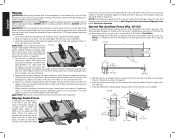
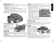
..., always use of the saw table top. 4. Lock the rip fence by pressing the rail lock lever down and your first two fingers and near the fence. 5. Keep the workpiece about 1/8" (3.2 mm) higher than 6" (152 mm) between the blade and the rip fence, use one hand, with a narrow ripping fence that also supports work support must be cut to put between the fence and the blade. 1. Never try to the fence as the saw table...
..., always use of the saw table top. 4. Lock the rip fence by pressing the rail lock lever down and your first two fingers and near the fence. 5. Keep the workpiece about 1/8" (3.2 mm) higher than 6" (152 mm) between the blade and the rip fence, use one hand, with a narrow ripping fence that also supports work support must be cut to put between the fence and the blade. 1. Never try to the fence as the saw table...
Instruction Manual
Page 13
... blade. Keep the workpiece an inch or so in Figure 36. Turn the switch off gauge, the block must never be square. If the blade guard assembly contacts the blade, place the workpiece under the blade guard assembly, not touching the blade, before starting the motor. CAUTION: Certain workpiece shapes, such as crosscutting except that the blade is cut to speed. 5. WARNING: NEVER use the fence as a cut -off , while the power is set...
... blade. Keep the workpiece an inch or so in Figure 36. Turn the switch off gauge, the block must never be square. If the blade guard assembly contacts the blade, place the workpiece under the blade guard assembly, not touching the blade, before starting the motor. CAUTION: Certain workpiece shapes, such as crosscutting except that the blade is cut to speed. 5. WARNING: NEVER use the fence as a cut -off , while the power is set...
Instruction Manual
Page 14
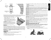
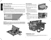
Compound Mitering and dust collection port. Dimensions for making a typical featherboard are shown in front of the blade. Make the featherboard from a straight piece of wood that the leading edge of knots and cracks. Clamp the featherboard to the fence and table so that is free of the featherboard will support the workpiece until the cut is complete (Fig. 42). Turn the saw 's dust collection bevel crosscutting and...
Compound Mitering and dust collection port. Dimensions for making a typical featherboard are shown in front of the blade. Make the featherboard from a straight piece of wood that the leading edge of knots and cracks. Clamp the featherboard to the fence and table so that is free of the featherboard will support the workpiece until the cut is complete (Fig. 42). Turn the saw 's dust collection bevel crosscutting and...
Instruction Manual
Page 15
..., repairs, maintenance and adjustment (including brush inspection and replacement) should be used with the performance of injury, only DEWALT recommended accessories should be hazardous. To reduce the risk of your purchase. Three Year Limited Warranty DEWALT will allow the assembly to products sold in the unlikely event a safety notification is a problem with this product. This warranty gives you specific legal rights and you for your DEWALT Power Tool, Laser...
..., repairs, maintenance and adjustment (including brush inspection and replacement) should be used with the performance of injury, only DEWALT recommended accessories should be hazardous. To reduce the risk of your purchase. Three Year Limited Warranty DEWALT will allow the assembly to products sold in the unlikely event a safety notification is a problem with this product. This warranty gives you specific legal rights and you for your DEWALT Power Tool, Laser...
Instruction Manual
Page 52
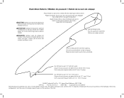
... contrachapada o madera blanda cuyo ancho sea igual o menor que el ancho del material que desea cortar. Corte aquí para empujar madera de 6,3 mm (1/4 pulg.). the "D" shaped air intake grill; the kit box configuration; ATTENTION: fabriquer le poussoir à partir de contreplaqué...hand will clear blade guard and rip fence. DEWALT Industrial Tool Co., 701 Joppa Road, Baltimore, MD 21286 (APR13) Part No. CAUTION: Make push stick from slipping. Push Stick Pattern / Modèle de poussoir / Patrón de la vara de empuje Adjust length of the material to be cut...
... contrachapada o madera blanda cuyo ancho sea igual o menor que el ancho del material que desea cortar. Corte aquí para empujar madera de 6,3 mm (1/4 pulg.). the "D" shaped air intake grill; the kit box configuration; ATTENTION: fabriquer le poussoir à partir de contreplaqué...hand will clear blade guard and rip fence. DEWALT Industrial Tool Co., 701 Joppa Road, Baltimore, MD 21286 (APR13) Part No. CAUTION: Make push stick from slipping. Push Stick Pattern / Modèle de poussoir / Patrón de la vara de empuje Adjust length of the material to be cut...
Parts Diagram
Page 3
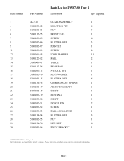
... DWE7480 Type 1 Description Qty Required GUARD ASSEMBLY 1 LOCATING PIN 4 NUT 4 FRONT RAIL 1 SCREW 6 FLAT WASHER 3 POINTER 1 SCREW 8 LOCK WASHER 11 RAIL 2 TABLE 1 REAR RAIL 1 NYLOCK NUT 1 FLAT WASHER 1 FLAT WASHER 6 COMPRESSION SPRING 1 ADJUSTING SHAFT 1 SHAFT 1 BUSHING 1 SHAFT 1 DOWEL PIN 2 SCREW 1 RAIL LOCK LEVER 1 FLAT WASHER 5 NUT 1 HEX NUT 6 PIVOT BRACKET 1 COPYRIGHT© 2005. Item Number 1 4 5 6 7 8 9 11 12 13 14 15 16 17 18 19 20 21 22 23 24 25 26 27 28 29 30 Part Number...
... DWE7480 Type 1 Description Qty Required GUARD ASSEMBLY 1 LOCATING PIN 4 NUT 4 FRONT RAIL 1 SCREW 6 FLAT WASHER 3 POINTER 1 SCREW 8 LOCK WASHER 11 RAIL 2 TABLE 1 REAR RAIL 1 NYLOCK NUT 1 FLAT WASHER 1 FLAT WASHER 6 COMPRESSION SPRING 1 ADJUSTING SHAFT 1 SHAFT 1 BUSHING 1 SHAFT 1 DOWEL PIN 2 SCREW 1 RAIL LOCK LEVER 1 FLAT WASHER 5 NUT 1 HEX NUT 6 PIVOT BRACKET 1 COPYRIGHT© 2005. Item Number 1 4 5 6 7 8 9 11 12 13 14 15 16 17 18 19 20 21 22 23 24 25 26 27 28 29 30 Part Number...

Parts Diagram
Page 4
... 5140032-57 Parts List for current parts information. Parts list, pricing, and availability subject to change. Please visit www.dewaltservicenet.com for DWE7480 Type 1 Description Qty Required NYLOCK NUT 2 FLAT WASHER 3 FENCE KNOB 1 PINNION GEAR 2 SCREW AND WASHER 1 BRACKET 2 BRACKET GAUGE 2 E-RING 2 DOWEL PIN 2 GEAR ROD 1 BEARING BLOCK 2 SPRING PLATE 2 O-RING 1 SCREW AND WASHER 4 NUT 1 SHOULDER SCREW 1 KNOB 1 HAND WHEEL 1 SHAFT 1 KEY 2 BEVEL GEAR 2 RING 2 LOCK NUT 1 SCREW AND WASHER 2 BEVEL HANDLE 1 SCREW 1 LOCKWASHER 1 COPYRIGHT...
... 5140032-57 Parts List for current parts information. Parts list, pricing, and availability subject to change. Please visit www.dewaltservicenet.com for DWE7480 Type 1 Description Qty Required NYLOCK NUT 2 FLAT WASHER 3 FENCE KNOB 1 PINNION GEAR 2 SCREW AND WASHER 1 BRACKET 2 BRACKET GAUGE 2 E-RING 2 DOWEL PIN 2 GEAR ROD 1 BEARING BLOCK 2 SPRING PLATE 2 O-RING 1 SCREW AND WASHER 4 NUT 1 SHOULDER SCREW 1 KNOB 1 HAND WHEEL 1 SHAFT 1 KEY 2 BEVEL GEAR 2 RING 2 LOCK NUT 1 SCREW AND WASHER 2 BEVEL HANDLE 1 SCREW 1 LOCKWASHER 1 COPYRIGHT...
Parts Diagram
Page 5
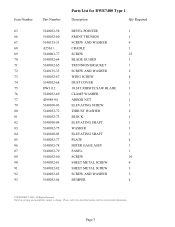
...for DWE7480 Type 1 Description Qty Required BEVEL POINTER 1 FRONT TRUNION 1 SCREW AND WASHER 4 CRADLE 1 SCREW 25 BLADE GUARD 1 TRUNNION BRACKET 1 SCREW AND WASHER 2 WING SCREW 4 DUST COVER 1 10 24T JOBSITE SAW BLADE 1 CLAMP WASHER 1 ARBOR NUT 1 ELEVATING SCREW 1 THRUST WASHER 2 BLOCK 1 ELEVATING SHAFT 1 WASHER 1 ELEVATING SHAFT 1 PLATE 4 MITER GAGE ASSY 1 PANEL 1 SCREW 10 SHEET METAL SCREW 4 SHEET METAL SCREW 3 SCREW AND WASHER 3 BUMPER 4 COPYRIGHT© 2005. Page 3 Parts list, pricing, and availability subject to change. Item...
...for DWE7480 Type 1 Description Qty Required BEVEL POINTER 1 FRONT TRUNION 1 SCREW AND WASHER 4 CRADLE 1 SCREW 25 BLADE GUARD 1 TRUNNION BRACKET 1 SCREW AND WASHER 2 WING SCREW 4 DUST COVER 1 10 24T JOBSITE SAW BLADE 1 CLAMP WASHER 1 ARBOR NUT 1 ELEVATING SCREW 1 THRUST WASHER 2 BLOCK 1 ELEVATING SHAFT 1 WASHER 1 ELEVATING SHAFT 1 PLATE 4 MITER GAGE ASSY 1 PANEL 1 SCREW 10 SHEET METAL SCREW 4 SHEET METAL SCREW 3 SCREW AND WASHER 3 BUMPER 4 COPYRIGHT© 2005. Page 3 Parts list, pricing, and availability subject to change. Item...

Parts Diagram
Page 7
... for DWE7480 Type 1 Description Qty Required LOCK WASHER 2 ARBOR 1 KEY 1 SCREW W/WASHER 3 GEAR CASE COVER 1 O-RING 1 BEARING 1 RING 1 RETAINING RING 1 GEAR 1 BEARING 1 O-RING 1 GEAR CASE 1 O-RING 1 BRUSH 2 BRUSH HOLDER 2 BRUSH CAP 2 FIELD CASE 1 SCREW AND WASHER 4 BEARING 1 ARMATURE ASSEMBLY 1 FIELD 1 SCREW AND WASHER 2 BAFFLE 1 BEARING 1 SET SCREW 2 BEVEL SCALE 1 COPYRIGHT© 2005. Item Number 128 ...-31 Parts List for current parts information. All Rights Reserved. Parts list, pricing, and availability subject to change.
... for DWE7480 Type 1 Description Qty Required LOCK WASHER 2 ARBOR 1 KEY 1 SCREW W/WASHER 3 GEAR CASE COVER 1 O-RING 1 BEARING 1 RING 1 RETAINING RING 1 GEAR 1 BEARING 1 O-RING 1 GEAR CASE 1 O-RING 1 BRUSH 2 BRUSH HOLDER 2 BRUSH CAP 2 FIELD CASE 1 SCREW AND WASHER 4 BEARING 1 ARMATURE ASSEMBLY 1 FIELD 1 SCREW AND WASHER 2 BAFFLE 1 BEARING 1 SET SCREW 2 BEVEL SCALE 1 COPYRIGHT© 2005. Item Number 128 ...-31 Parts List for current parts information. All Rights Reserved. Parts list, pricing, and availability subject to change.

Parts Diagram
Page 8
.... Please visit www.dewaltservicenet.com for DWE7480 Type 1 Description Qty Required DEWALT LABEL 1 SCALE LABEL 1 LABEL 1 WARNING LABEL 1 FENCE ASSEMBLY 1 PLATE 2 DOWEL PIN 2 SPRING PLATE 2 THROAT PLTE ASM 1 SCREW 4 SCREW 1 CAM 1 SPRING 1 SET SCREW 3 WARNING LABEL 1 WARNING LABEL 1 WARNING LABEL 1 STRAP CLAMP 1 SPRING CLIP 1 KNOB 1 LOCK WASHER 1 FLAT WASHER 1 E-RING 1 PLATE 1 PISTON 1 CLAMP ASSEMBLY 1 SHOULDER SCREW 2 COPYRIGHT© 2005. Parts list, pricing, and availability subject to change. Item Number 232 234 237 238 250 258...
.... Please visit www.dewaltservicenet.com for DWE7480 Type 1 Description Qty Required DEWALT LABEL 1 SCALE LABEL 1 LABEL 1 WARNING LABEL 1 FENCE ASSEMBLY 1 PLATE 2 DOWEL PIN 2 SPRING PLATE 2 THROAT PLTE ASM 1 SCREW 4 SCREW 1 CAM 1 SPRING 1 SET SCREW 3 WARNING LABEL 1 WARNING LABEL 1 WARNING LABEL 1 STRAP CLAMP 1 SPRING CLIP 1 KNOB 1 LOCK WASHER 1 FLAT WASHER 1 E-RING 1 PLATE 1 PISTON 1 CLAMP ASSEMBLY 1 SHOULDER SCREW 2 COPYRIGHT© 2005. Parts list, pricing, and availability subject to change. Item Number 232 234 237 238 250 258...


