
Instruction Manual
Page 3
... distance from tool before operating product. Do not change the plug in any way. • KEEP GUARDS IN PLACE and in the outlet, reverse the plug. Form habit of electric shock. Repair or replace damaged cords. The smaller the gauge number of the wire, the greater the capacity of the primary insulation within the tool. Important Safety Instructions WARNING: Read all instructions listed below describe the...
... distance from tool before operating product. Do not change the plug in any way. • KEEP GUARDS IN PLACE and in the outlet, reverse the plug. Form habit of electric shock. Repair or replace damaged cords. The smaller the gauge number of the wire, the greater the capacity of the primary insulation within the tool. Important Safety Instructions WARNING: Read all instructions listed below describe the...
Instruction Manual
Page 4
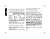
... the wheel. Additional Safety Rules for Chop Saw • Always wear proper eye and respiratory protection. • Before using your chop saw periodically following table shows the correct size to a complete stop the tool and inspect the wheel for Cord Sets Volts Total Length of parts, mounting, and any other part that may get caught in moving parts, breakage of Cord in this manual. • Do not remove wheel guards or base. 2 The...
... the wheel. Additional Safety Rules for Chop Saw • Always wear proper eye and respiratory protection. • Before using your chop saw periodically following table shows the correct size to a complete stop the tool and inspect the wheel for Cord Sets Volts Total Length of parts, mounting, and any other part that may get caught in moving parts, breakage of Cord in this manual. • Do not remove wheel guards or base. 2 The...

Instruction Manual
Page 5
... area, and work . DO NOT USE TOOTHED BLADES. CAUTION: Wear appropriate hearing protection during use the side of work with this tool. • NEVER CUT MAGNESIUM WITH THIS TOOL. • Use chop saw off before removing any pieces from power sanding, sawing, grinding, drilling, and other masonry products, and • arsenic and chromium from these clamps and make a dry run before making a cut. • Use only 14" type 1 wheels rated at...
... area, and work . DO NOT USE TOOTHED BLADES. CAUTION: Wear appropriate hearing protection during use the side of work with this tool. • NEVER CUT MAGNESIUM WITH THIS TOOL. • Use chop saw off before removing any pieces from power sanding, sawing, grinding, drilling, and other masonry products, and • arsenic and chromium from these clamps and make a dry run before making a cut. • Use only 14" type 1 wheels rated at...

Instruction Manual
Page 7
Chain lock B. Base E. Wheel lock lever M. Jam nut Q. MAXIMUM CUTTING CAPACITY NOTE: Capacity shown on chart assumes no wheel wear and optimum fence position. Vise G. 8mm hex wrench H. Guard L. Trigger switch O. Use the cutting capacity chart to determine total maximum size of power and overheating. Power Supply Be sure your power supply agrees with a new wheel. Fence bolts A voltage decrease of more than 10% will cause a loss of cuts that can be made...
Chain lock B. Base E. Wheel lock lever M. Jam nut Q. MAXIMUM CUTTING CAPACITY NOTE: Capacity shown on chart assumes no wheel wear and optimum fence position. Vise G. 8mm hex wrench H. Guard L. Trigger switch O. Use the cutting capacity chart to determine total maximum size of power and overheating. Power Supply Be sure your power supply agrees with a new wheel. Fence bolts A voltage decrease of more than 10% will cause a loss of cuts that can be made...

Instruction Manual
Page 8
... SPACER BLOCK 6 Material Clamping and Supporting • Angles are best clamped and cut -off end should be free to fall downward to increase wheel utilization (Fig. 2). • Long workpieces must be supported by a block so it will then pivot upward. English Standard Equipment 1 14" (355mm) metal cutting abrasive wheel 1 Wheel wrench 1 Instruction manual To Carry (Fig. 1) Fold down . Use the chain lock (A) to lock arm down unit...
... SPACER BLOCK 6 Material Clamping and Supporting • Angles are best clamped and cut -off end should be free to fall downward to increase wheel utilization (Fig. 2). • Long workpieces must be supported by a block so it will then pivot upward. English Standard Equipment 1 14" (355mm) metal cutting abrasive wheel 1 Wheel wrench 1 Instruction manual To Carry (Fig. 1) Fold down . Use the chain lock (A) to lock arm down unit...

Instruction Manual
Page 9
... change desired cutting angle and to the fence when making any adjustments or removing or installing attachments or accessories. Be sure the trigger switch is set at the factory for a new 14" (355mm) wheel to prevent wheel from cutting into work by using crank (H). Place a square against the wheel and adjust fence against the square. Securely tighten both fence bolts in provided locations. Insert both fence bolts before use. CAUTION: When changing to prevent cutting into base. Fence Operation WARNING: Turn off...
... change desired cutting angle and to the fence when making any adjustments or removing or installing attachments or accessories. Be sure the trigger switch is set at the factory for a new 14" (355mm) wheel to prevent wheel from cutting into work by using crank (H). Place a square against the wheel and adjust fence against the square. Securely tighten both fence bolts in provided locations. Insert both fence bolts before use. CAUTION: When changing to prevent cutting into base. Fence Operation WARNING: Turn off...

Instruction Manual
Page 10
... use of tool, install a standard padlock (not included) into power supply. 1. Loosen the bolt (T) counterclockwise in the trigger. PROCEDURE FOR PERMANENT MOUNTING 1. Removal and Installation of the abrasive wheel with a new abrasive wheel. Push in inside flange (S) to a stop. Install the new abrasive wheel by hand until it has coasted to lock wheel. Insert 1/4-20 screws down through the holes in the base and through the work surface (under the base...
... use of tool, install a standard padlock (not included) into power supply. 1. Loosen the bolt (T) counterclockwise in the trigger. PROCEDURE FOR PERMANENT MOUNTING 1. Removal and Installation of the abrasive wheel with a new abrasive wheel. Push in inside flange (S) to a stop. Install the new abrasive wheel by hand until it has coasted to lock wheel. Insert 1/4-20 screws down through the holes in the base and through the work surface (under the base...

Instruction Manual
Page 11
... the tool. WARNING: Never use solvents or other qualified service organizations, always using identical replacement parts. 9 These chemicals may weaken the plastic materials used in the OFF position. Never let any adjustments or removing or installing attachments or accessories. Cut two boards approximately 20" long x 2" high x 4" wide (508 x 50.8 x 101.6mm). 2. FIG. 11 W X .2" (6mm) X Brushes should be replaced. MAINTENANCE Motor Brush Inspection and Replacement (Fig. 11) WARNING: Turn off...
... the tool. WARNING: Never use solvents or other qualified service organizations, always using identical replacement parts. 9 These chemicals may weaken the plastic materials used in the OFF position. Never let any adjustments or removing or installing attachments or accessories. Cut two boards approximately 20" long x 2" high x 4" wide (508 x 50.8 x 101.6mm). 2. FIG. 11 W X .2" (6mm) X Brushes should be replaced. MAINTENANCE Motor Brush Inspection and Replacement (Fig. 11) WARNING: Turn off...

Instruction Manual
Page 12
... with a receipt for warranty information. Use only high-strength Type 1 organic bonded wheels rated 4100 rpm or higher. Three Year Limited Warranty DEWALT will maintain the tool and replace worn parts caused by normal use, for free, any time during the first year after purchase. 90 DAY MONEY BACK GUARANTEE If you are covered by our: 1 YEAR FREE SERVICE DEWALT will repair, without charge, any...
... with a receipt for warranty information. Use only high-strength Type 1 organic bonded wheels rated 4100 rpm or higher. Three Year Limited Warranty DEWALT will maintain the tool and replace worn parts caused by normal use, for free, any time during the first year after purchase. 90 DAY MONEY BACK GUARANTEE If you are covered by our: 1 YEAR FREE SERVICE DEWALT will repair, without charge, any...

Instruction Manual
Page 13
... electric company. 3. English Troubleshooting Guide TROUBLE! Tool not plugged in saw. 2. Replace fuse or reset circuit breaker. 3. WHAT TO DO... 1. Tool not mounted securely to Material Clamping and Supporting, page 6. 11 WHAT TO DO... 1. Have cord replaced by the generator. Glazed wheel. 2. TROUBLE! TROUBLE! Dress the wheel or replace with adequate size cord. Firmly clamp and support workpiece. Cord damaged. 4. Brushes worn out. Low generator voltage. TOOL VIBRATES EXCESSIVELY DURING CUT WHAT'S WRONG? 1. TROUBLE! Replace brushes. BLADE...
... electric company. 3. English Troubleshooting Guide TROUBLE! Tool not plugged in saw. 2. Replace fuse or reset circuit breaker. 3. WHAT TO DO... 1. Tool not mounted securely to Material Clamping and Supporting, page 6. 11 WHAT TO DO... 1. Have cord replaced by the generator. Glazed wheel. 2. TROUBLE! TROUBLE! Dress the wheel or replace with adequate size cord. Firmly clamp and support workpiece. Cord damaged. 4. Brushes worn out. Low generator voltage. TOOL VIBRATES EXCESSIVELY DURING CUT WHAT'S WRONG? 1. TROUBLE! Replace brushes. BLADE...

Instruction Manual
Page 14
... Material Clamping and Supporting, page 6. 2. TROUBLE! Check and adjust. See Fence Operation on the arm, unlock the chain lock and raise arm. Tighten vise clamping. 3. MATERIAL MOVES DURING CUT WHAT'S WRONG? 1. Vise too loose. 3. Reduce cutting force; WHAT TO DO... 1. WHAT TO DO... 1. Reduce cutting force. 12 See Material Clamping and Supporting, page 6. CANNOT MOVE ARM WHAT'S WRONG? 1. Make sure material is engaged. English Troubleshooting Guide...
... Material Clamping and Supporting, page 6. 2. TROUBLE! Check and adjust. See Fence Operation on the arm, unlock the chain lock and raise arm. Tighten vise clamping. 3. MATERIAL MOVES DURING CUT WHAT'S WRONG? 1. Vise too loose. 3. Reduce cutting force; WHAT TO DO... 1. WHAT TO DO... 1. Reduce cutting force. 12 See Material Clamping and Supporting, page 6. CANNOT MOVE ARM WHAT'S WRONG? 1. Make sure material is engaged. English Troubleshooting Guide...

Instruction Manual
Page 44
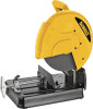
N096693 D28710 Copyright © 2011 DEWALT The following are trademarks for one or more DEWALT power tools: the yellow and black color scheme, the "D" shaped air intake grill, the array of pyramids on the handgrip, the kit box configuration, and the array of lozenge-shaped humps on the surface of the tool. DEWALT Industrial Tool Co., 701 East Joppa Road, Baltimore, MD 21286 (APR11) Part No.
N096693 D28710 Copyright © 2011 DEWALT The following are trademarks for one or more DEWALT power tools: the yellow and black color scheme, the "D" shaped air intake grill, the array of pyramids on the handgrip, the kit box configuration, and the array of lozenge-shaped humps on the surface of the tool. DEWALT Industrial Tool Co., 701 East Joppa Road, Baltimore, MD 21286 (APR11) Part No.


