
Owners Manual
Page 1
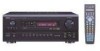
...~ PAGINA 162 PAGINA 163 ~ PAGINA 202 PAGINA 203 ~ PAGINA 242 SIDA 243 ~ SIDA 282 AV SURROUND RECEIVER AVR-3802 OPERATING INSTRUCTIONS BEDIENUNGSANLEITUNG MODE D'EMPLOI ISTRUZIONI PER L'USO INSTRUCCIONES DE OPERACION GEBRUIKSAANWIJZING BRUKSANVISNING PRECISION AUDIO COMPONENT / AV SURROUND RECEIVER AVR-3802 FUNCTION REMOTE SENSOR ON / STANDBY AUTO SIGNAL DIGITAL SURROUND BACK CH OUTPUT INPUT PCM DTS SIGNAL... MODE SELECT SURROUND PARAMETER CH VOL TONE CONTROL POWER OFF ON / SOURCE RC-884 REMOTE CONTROL UNIT TV CD CDR/MD/ TAPE RECEIVER VCR DBS/CABLE VDP DVD DISPLAY SURR.
...~ PAGINA 162 PAGINA 163 ~ PAGINA 202 PAGINA 203 ~ PAGINA 242 SIDA 243 ~ SIDA 282 AV SURROUND RECEIVER AVR-3802 OPERATING INSTRUCTIONS BEDIENUNGSANLEITUNG MODE D'EMPLOI ISTRUZIONI PER L'USO INSTRUCCIONES DE OPERACION GEBRUIKSAANWIJZING BRUKSANVISNING PRECISION AUDIO COMPONENT / AV SURROUND RECEIVER AVR-3802 FUNCTION REMOTE SENSOR ON / STANDBY AUTO SIGNAL DIGITAL SURROUND BACK CH OUTPUT INPUT PCM DTS SIGNAL... MODE SELECT SURROUND PARAMETER CH VOL TONE CONTROL POWER OFF ON / SOURCE RC-884 REMOTE CONTROL UNIT TV CD CDR/MD/ TAPE RECEIVER VCR DBS/CABLE VDP DVD DISPLAY SURR.

Owners Manual
Page 2
The exclamation point within the product's enclosure that this product, to which this declaration relates, is in un mobile per la spina quando scollegate il cavo dalla presa. • Maneje el cordón de energía con cuidado. Beachten Sie, daß eine ausreichend Luftzirkulation gewährleistet wird, wenn das Gerät auf ein Regal gestellt wird. • Eviter des températures élevées Tenir compte d'une dispersion de chaleur suffisante lors de l'installation sur une étagère. • Evitate di esporre l'unità a temperature alte. Hold the ...
The exclamation point within the product's enclosure that this product, to which this declaration relates, is in un mobile per la spina quando scollegate il cavo dalla presa. • Maneje el cordón de energía con cuidado. Beachten Sie, daß eine ausreichend Luftzirkulation gewährleistet wird, wenn das Gerät auf ein Regal gestellt wird. • Eviter des températures élevées Tenir compte d'une dispersion de chaleur suffisante lors de l'installation sur une étagère. • Evitate di esporre l'unità a temperature alte. Hold the ...
Owners Manual
Page 3
... n Part Names and Functions 8, 9 m Setting up during this unit as far as providing outstanding high fidelity reproduction of your purchase of the AVR-3802. 2 To be sure to provide superb surround sound listening with the warranty in a safe place. • Note that you for several seconds ... or more wall 3 CAUTIONS ON HANDLING • Switching the input function when input jacks are greatly reduced for choosing the DENON AVR-3802 Digital Surround A / V receiver. Always wait 3 As this unit's power cord and input/output connection cords. • Noise or disturbance tends to the...
... n Part Names and Functions 8, 9 m Setting up during this unit as far as providing outstanding high fidelity reproduction of your purchase of the AVR-3802. 2 To be sure to provide superb surround sound listening with the warranty in a safe place. • Note that you for several seconds ... or more wall 3 CAUTIONS ON HANDLING • Switching the input function when input jacks are greatly reduced for choosing the DENON AVR-3802 Digital Surround A / V receiver. Always wait 3 As this unit's power cord and input/output connection cords. • Noise or disturbance tends to the...
Owners Manual
Page 4
... regular stereo sources. 6. NOTE: Only use the surround channel(s) to composite video and "S" video switching, the AVR-3802 provides 2 sets of component video (Y, PB/CB, PR/CR) inputs for connections to realize. Connecting the pre...in the AC cord until all connections have been completed. • Be sure to this terminal. The DENON AVR-3802 provides the ability to connect two different sets of component video outputs to this unit on -axis localization ... power is turned on and off in your AV theater room, so that offers improvements over conventional Dolby Pro Logic.
... regular stereo sources. 6. NOTE: Only use the surround channel(s) to composite video and "S" video switching, the AVR-3802 provides 2 sets of component video (Y, PB/CB, PR/CR) inputs for connections to realize. Connecting the pre...in the AC cord until all connections have been completed. • Be sure to this terminal. The DENON AVR-3802 provides the ability to connect two different sets of component video outputs to this unit on -axis localization ... power is turned on and off in your AV theater room, so that offers improvements over conventional Dolby Pro Logic.

Owners Manual
Page 5
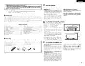
Connecting a monitor TV MONITOR OUT • Connect the TV's video input jack (VIDEO INPUT) to the VIDEO MONITOR OUT jack using a S jack connection cord. VIDEO DVD IN jack using S-jacks This unit's S-jacks (input and output) and video pin jacks (input and output) have independent circuit structures, so that is also possible to connect a video disc player, DVD player, video camcorder, game machine, etc., to the S-VIDEO MONITOR OUT jack using a 75 Ω/ohms video coaxial pin plug cord. Monitor TV AUDIO VIDEO B OUT R L OUT DVD player or video disc player (VDP), etc. For...
Connecting a monitor TV MONITOR OUT • Connect the TV's video input jack (VIDEO INPUT) to the VIDEO MONITOR OUT jack using a S jack connection cord. VIDEO DVD IN jack using S-jacks This unit's S-jacks (input and output) and video pin jacks (input and output) have independent circuit structures, so that is also possible to connect a video disc player, DVD player, video camcorder, game machine, etc., to the S-VIDEO MONITOR OUT jack using a 75 Ω/ohms video coaxial pin plug cord. Monitor TV AUDIO VIDEO B OUT R L OUT DVD player or video disc player (VDP), etc. For...

Owners Manual
Page 6
...) video jacks are labeled Y, CB, CR, or Y, Pb, Pr, or Y, R-Y, B-Y. In addition, the video signals input to the color difference (component) video jacks. • The AVR-3802's on some TVs, monitors or video components ("CR, CB and Y", "R-Y, B-Y and Y", "Pr, Pb and Y", etc.). Connecting the antenna terminals DIRECTION OF BROADCASTING STATION FM ANTENNA...
...) video jacks are labeled Y, CB, CR, or Y, Pb, Pr, or Y, R-Y, B-Y. In addition, the video signals input to the color difference (component) video jacks. • The AVR-3802's on some TVs, monitors or video components ("CR, CB and Y", "R-Y, B-Y and Y", "Pr, Pb and Y", etc.). Connecting the antenna terminals DIRECTION OF BROADCASTING STATION FM ANTENNA...

Owners Manual
Page 7
... be activated if the set , then turn the power back on operations using the external input (EXT. Note on . Turn off the power and contact a DENON service center. R L R L RL Decoder with a high-speed protection circuit.
... be activated if the set , then turn the power back on operations using the external input (EXT. Note on . Turn off the power and contact a DENON service center. R L R L RL Decoder with a high-speed protection circuit.

Owners Manual
Page 8
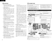
... AND FUNCTIONS Front Panel • For details on the screen may be changed to use Surround back with built-in parentheses ( ). @9 @8 @7 @6 @5 @4 @3 @2 @1 @0 !9 PRECISION AUDIO COMPONENT / AV SURROUND RECEIVER AVR-3802 FUNCTION REMOTE SENSOR ON / STANDBY AUTO SIGNAL DIGITAL SURROUND BACK CH OUTPUT INPUT PCM DTS SIGNAL DETECT SOURCE TUNING PRESET REC / 6.1 / 7.1 MULTI SURROUND A SURROUND SPEAKER...
... AND FUNCTIONS Front Panel • For details on the screen may be changed to use Surround back with built-in parentheses ( ). @9 @8 @7 @6 @5 @4 @3 @2 @1 @0 !9 PRECISION AUDIO COMPONENT / AV SURROUND RECEIVER AVR-3802 FUNCTION REMOTE SENSOR ON / STANDBY AUTO SIGNAL DIGITAL SURROUND BACK CH OUTPUT INPUT PCM DTS SIGNAL DETECT SOURCE TUNING PRESET REC / 6.1 / 7.1 MULTI SURROUND A SURROUND SPEAKER...
Owners Manual
Page 9
... when the controls on the remote control unit or main unit are selected automatically according to the surround Surround mode. FM stations are received automatically and stored in order to obtain optimum effects. SETUP TUNING MENU OSD RETURN A/B MEMORY BAND MODE CHANNEL VOLUME TUNING + + ...(see pages 4 to 8), make the various settings described below which the audio signals are required to set up the listening room's AV system centered around the AVR-3802. • Use the following buttons to set up and down on the screen. Yes Small Small / 2spkrs w (Surround Use ...
... when the controls on the remote control unit or main unit are selected automatically according to the surround Surround mode. FM stations are received automatically and stored in order to obtain optimum effects. SETUP TUNING MENU OSD RETURN A/B MEMORY BAND MODE CHANNEL VOLUME TUNING + + ...(see pages 4 to 8), make the various settings described below which the audio signals are required to set up the listening room's AV system centered around the AVR-3802. • Use the following buttons to set up and down on the screen. Yes Small Small / 2spkrs w (Surround Use ...

Owners Manual
Page 10
...the video monitor output jack, do not connect a cord to the S-VIDEO MONITOR OUT jack. (For details, see page 16.) • The AVR-3802's on-screen display function is an example of the basic layout for different sources by switching between two systems of eight speaker systems and a television... Enter the setting. For example, if the TV monitor is also possible to use as possible. Surround speaker systems 3 ENTER SHIFT With the AVR-3802 it may be difficult to read small characters on TVs with the front of a video component. The System Setup Menu reappears. Setting the type...
...the video monitor output jack, do not connect a cord to the S-VIDEO MONITOR OUT jack. (For details, see page 16.) • The AVR-3802's on-screen display function is an example of the basic layout for different sources by switching between two systems of eight speaker systems and a television... Enter the setting. For example, if the TV monitor is also possible to use as possible. Surround speaker systems 3 ENTER SHIFT With the AVR-3802 it may be difficult to read small characters on TVs with the front of a video component. The System Setup Menu reappears. Setting the type...
Owners Manual
Page 11
A Surround back Sp. NOTE: • Select "Large" or "Small" not according to the actual size of below frequency set for both surround speakers A and B If "Small" is set for either surround speakers A or B, the output is the same as not to damage the speakers) to determine the proper setting. • Parameters Large Select this screen preset the surround speakers to "Yes", the set for the Crossover Frequency mode. When this setting is selected, low frequencies of the speaker but according to the speaker's capacity for playing low frequency (bass sound below the frequency set ...
A Surround back Sp. NOTE: • Select "Large" or "Small" not according to the actual size of below frequency set for both surround speakers A and B If "Small" is set for either surround speakers A or B, the output is the same as not to damage the speakers) to determine the proper setting. • Parameters Large Select this screen preset the surround speakers to "Yes", the set for the Crossover Frequency mode. When this setting is selected, low frequencies of the speaker but according to the speaker's capacity for playing low frequency (bass sound below the frequency set ...

Owners Manual
Page 12
NOTE: For ordinary speaker systems, we recommend setting the crossover frequency to a high frequency may result in a decrease of the actual volume of the low frequency range. • Selection of the "LFE " play mode will play the low frequency signal range of the surround back speaker in the 6.1-channel surround mode using small speakers, however, setting the crossover frequency to 80 Hz. Therefore, the low frequency signal range that are played from the subwoofer channel are produced simultaneously from those channels and the subwoofer channel. w Non-Flag Source SBch Output MTRX ON: ...
NOTE: For ordinary speaker systems, we recommend setting the crossover frequency to a high frequency may result in a decrease of the actual volume of the low frequency range. • Selection of the "LFE " play mode will play the low frequency signal range of the surround back speaker in the 6.1-channel surround mode using small speakers, however, setting the crossover frequency to 80 Hz. Therefore, the low frequency signal range that are played from the subwoofer channel are produced simultaneously from those channels and the subwoofer channel. w Non-Flag Source SBch Output MTRX ON: ...

Owners Manual
Page 13
... to the test tones produced from the remote control unit. (For details, see page 9). 5 TUNING BAND MODE TUNING TUNING BAND MODE TUNING Select "Surr. The AVR-3802 automatically sets the optimum surround delay time for "Default", the settings are reset to the Channel Level screen. 3 Select "Test Tone Mode". Sp.: A+B Adjusts the...
... to the test tones produced from the remote control unit. (For details, see page 9). 5 TUNING BAND MODE TUNING TUNING BAND MODE TUNING Select "Surr. The AVR-3802 automatically sets the optimum surround delay time for "Default", the settings are reset to the Channel Level screen. 3 Select "Test Tone Mode". Sp.: A+B Adjusts the...

Owners Manual
Page 14
...between a digital audio source (stereo - 2 channel) and a digital audio recorder. • Do not connect the output of the AVR-3802 for natural balance. Because adjusting the subwoofer level test tone by ear so the sound levels are automatically emitted from the different speakers ...jack other digital recorder. ENGLISH 7 Select "Yes". b. The "Channel Level" screen reappears. NOTES: • The OPTICAL 3 jacks on the AVR-3802's rear panel are emitted from the different speakers. TUNING BAND MODE TUNING 8 a. Then, whenever you adjust the channel levels while in the ...
...between a digital audio source (stereo - 2 channel) and a digital audio recorder. • Do not connect the output of the AVR-3802 for natural balance. Because adjusting the subwoofer level test tone by ear so the sound levels are automatically emitted from the different speakers ...jack other digital recorder. ENGLISH 7 Select "Yes". b. The "Channel Level" screen reappears. NOTES: • The OPTICAL 3 jacks on the AVR-3802's rear panel are emitted from the different speakers. TUNING BAND MODE TUNING 8 a. Then, whenever you adjust the channel levels while in the ...

Owners Manual
Page 15
... tuning" operation to 8. Variable: The level can no need to screen. The System Setup Menu reappears. The display automatically switches to change them unless different AV components are connected or the speakers are made, there is completed. Once these settings are repositioned. 15 BAND MODE TUNING 2 ENTER SHIFT Press the ENTER...
... tuning" operation to 8. Variable: The level can no need to screen. The System Setup Menu reappears. The display automatically switches to change them unless different AV components are connected or the speakers are made, there is completed. Once these settings are repositioned. 15 BAND MODE TUNING 2 ENTER SHIFT Press the ENTER...
Owners Manual
Page 16
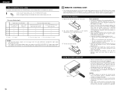
...control unit. • The batteries should leak, carefully wipe the fluid off . • On-screen display signals Signals input to operate non-Denon remote control compatible products. Using the remote control unit B Approx. 7 m 30° 30° • Point the remote control unit... remote control unit if the remote sensor is not pointed directly at the remote sensor. • The remote control unit can be used to the AVR-3802 VIDEO signal input jack (yellow) S-video signal input jack 1 E E 2 C E 3 E C 4 C C (C: Signal E: No signal) On-screen display signal output...
...control unit. • The batteries should leak, carefully wipe the fluid off . • On-screen display signals Signals input to operate non-Denon remote control compatible products. Using the remote control unit B Approx. 7 m 30° 30° • Point the remote control unit... remote control unit if the remote sensor is not pointed directly at the remote sensor. • The remote control unit can be used to the AVR-3802 VIDEO signal input jack (yellow) S-video signal input jack 1 E E 2 C E 3 E C 4 C C (C: Signal E: No signal) On-screen display signal output...
Owners Manual
Page 17
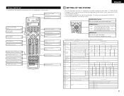
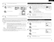
.... • For details, refer to the component's operating instructions. POWER OFF ON / SOURCE RC-884 REMOTE CONTROL UNIT 1 TV CD CDR/MD/ TAPE RECEIVER VCR DBS/CABLE VDP DVD DISPLAY SURR. CD player (CD) system buttons SETUP TUNING RETURN A/B MEMORY BAND MODE CHANNEL VOLUME TUNING + + SKIP ENTER -... pressed buttons are of makes listed on the included list of the component whose codes you want to store in the memory. Operating DENON audio components 1 Use the mode selector buttons to select the component you want to store in the memory, then press the ENTER button...
.... • For details, refer to the component's operating instructions. POWER OFF ON / SOURCE RC-884 REMOTE CONTROL UNIT 1 TV CD CDR/MD/ TAPE RECEIVER VCR DBS/CABLE VDP DVD DISPLAY SURR. CD player (CD) system buttons SETUP TUNING RETURN A/B MEMORY BAND MODE CHANNEL VOLUME TUNING + + SKIP ENTER -... pressed buttons are of makes listed on the included list of the component whose codes you want to store in the memory. Operating DENON audio components 1 Use the mode selector buttons to select the component you want to store in the memory, then press the ENTER button...
Owners Manual
Page 18
...follows upon shipment from the factory and after resetting: TV, VCR HITACHI CD, MD, TAPE, CDR, VDP, DVD, DVD SETUP .........DENON DBS GENERAL INSTRUMENT CABLE JERROLD Checking the preset memory settings 1 4 Press the power ON/SOURCE button and the OFF button at the...) 2 : Stop 1 : Play 3 : Pause Channel +, - : Channels POWER OFF ON / SOURCE RC-884 REMOTE CONTROL UNIT TV CD CDR/MD/ TAPE RECEIVER VCR DBS/CABLE VDP DVD DISPLAY SURR. SETUP TUNING MENU OSD RETURN A/B MEMORY BAND CHANNEL MODE VOLUME TUNING + + SKIP ENTER - SKIP SHIFT MUTING TUNER 1 PHONO...
...follows upon shipment from the factory and after resetting: TV, VCR HITACHI CD, MD, TAPE, CDR, VDP, DVD, DVD SETUP .........DENON DBS GENERAL INSTRUMENT CABLE JERROLD Checking the preset memory settings 1 4 Press the power ON/SOURCE button and the OFF button at the...) 2 : Stop 1 : Play 3 : Pause Channel +, - : Channels POWER OFF ON / SOURCE RC-884 REMOTE CONTROL UNIT TV CD CDR/MD/ TAPE RECEIVER VCR DBS/CABLE VDP DVD DISPLAY SURR. SETUP TUNING MENU OSD RETURN A/B MEMORY BAND CHANNEL MODE VOLUME TUNING + + SKIP ENTER - SKIP SHIFT MUTING TUNER 1 PHONO...
Owners Manual
Page 19
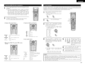
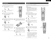
... - SETUP TUNING MENU OSD RETURN A/B MEMORY BAND MODE CHANNEL VOLUME TUNING + + SKIP ENTER - ENGLISH Learning function If your AV component is not a Denon product or if it cannot be operated using the preset memory, it can be controlled with a system call signals can be "...control unit is displayed. 1 POWER OFF ON / SOURCE RC-884 REMOTE CONTROL UNIT 7 3, 4, 5 2, 3, 5, 6, 8 TV CD CDR/MD/ TAPE RECEIVER VCR DBS/CABLE VDP DVD DISPLAY SURR. When the enter button is pressed, the button registering mode (step 6) is displayed. SKIP SHIFT MUTING TUNER 1 PHONO...
... - SETUP TUNING MENU OSD RETURN A/B MEMORY BAND MODE CHANNEL VOLUME TUNING + + SKIP ENTER - ENGLISH Learning function If your AV component is not a Denon product or if it cannot be operated using the preset memory, it can be controlled with a system call signals can be "...control unit is displayed. 1 POWER OFF ON / SOURCE RC-884 REMOTE CONTROL UNIT 7 3, 4, 5 2, 3, 5, 6, 8 TV CD CDR/MD/ TAPE RECEIVER VCR DBS/CABLE VDP DVD DISPLAY SURR. When the enter button is pressed, the button registering mode (step 6) is displayed. SKIP SHIFT MUTING TUNER 1 PHONO...
Owners Manual
Page 20
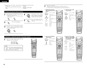
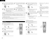
... BAND MODE TUNING ENTER SHIFT 1 POWER OFF ON / SOURCE RC-884 REMOTE CONTROL UNIT 3, 4, 5 2, 3, 4, 6, 7 TV CD CDR/MD/ TAPE RECEIVER VCR DBS/CABLE VDP DVD DISPLAY SURR. SETUP TUNING MENU OSD RETURN A/B MEMORY BAND MODE CHANNEL VOLUME TUNING + + SKIP ENTER - SYS MODE SYS CALL 1 ... ON / SOURCE RC-884 REMOTE CONTROL UNIT 3, 4, 5 2, 3, 4, 5, 6 TV CD CDR/MD/ TAPE RECEIVER VCR DBS/CABLE VDP DVD DISPLAY SURR. TV CD CDR/MD/ TAPE RECEIVER TUNING BAND MODE TUNING ENTER SHIFT VCR DBS/CABLE VDP DVD w Press the buttons with the remote control signals...
... BAND MODE TUNING ENTER SHIFT 1 POWER OFF ON / SOURCE RC-884 REMOTE CONTROL UNIT 3, 4, 5 2, 3, 4, 6, 7 TV CD CDR/MD/ TAPE RECEIVER VCR DBS/CABLE VDP DVD DISPLAY SURR. SETUP TUNING MENU OSD RETURN A/B MEMORY BAND MODE CHANNEL VOLUME TUNING + + SKIP ENTER - SYS MODE SYS CALL 1 ... ON / SOURCE RC-884 REMOTE CONTROL UNIT 3, 4, 5 2, 3, 4, 5, 6 TV CD CDR/MD/ TAPE RECEIVER VCR DBS/CABLE VDP DVD DISPLAY SURR. TV CD CDR/MD/ TAPE RECEIVER TUNING BAND MODE TUNING ENTER SHIFT VCR DBS/CABLE VDP DVD w Press the buttons with the remote control signals...
