
Service Manual
Page 7
...card reader driver...83 Downloading the chipset driver...83 Downloading the network driver...83 Chapter 51: System setup...84 Boot Sequence...84 Navigation keys...84 BIOS overview...84 Entering BIOS setup program...84 System Setup Options...85 System and setup password...87 Assigning a system setup password...88 Deleting or changing an existing system setup password 88 Clearing CMOS settings...88 Clearing forgotten passwords...89 Chapter 52: Troubleshooting...92 Enhanced Pre-Boot System Assessment (ePSA) diagnostics 92 Running the ePSA Diagnostics...92 Diagnostics...92 Flashing BIOS (USB key...
...card reader driver...83 Downloading the chipset driver...83 Downloading the network driver...83 Chapter 51: System setup...84 Boot Sequence...84 Navigation keys...84 BIOS overview...84 Entering BIOS setup program...84 System Setup Options...85 System and setup password...87 Assigning a system setup password...88 Deleting or changing an existing system setup password 88 Clearing CMOS settings...88 Clearing forgotten passwords...89 Chapter 52: Troubleshooting...92 Enhanced Pre-Boot System Assessment (ePSA) diagnostics 92 Running the ePSA Diagnostics...92 Diagnostics...92 Flashing BIOS (USB key...
Service Manual
Page 8
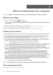
... ordered. CAUTION: Press and eject any installed card from potential damage and to servicing that the ports and connectors are using a wrist grounding strap or by its metal mounting bracket. Click Start > Power > Shut down your computer from the media-card reader. After you must disengage before opening the computer cover or panels. Safety instructions Use the following tools: 8 Before working inside your computer, read the safety information...
... ordered. CAUTION: Press and eject any installed card from potential damage and to servicing that the ports and connectors are using a wrist grounding strap or by its metal mounting bracket. Click Start > Power > Shut down your computer from the media-card reader. After you must disengage before opening the computer cover or panels. Safety instructions Use the following tools: 8 Before working inside your computer, read the safety information...
Service Manual
Page 10
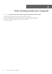
Connect your computer and all screws and ensure that you removed before working on your computer. 4. Replace all attached devices to their electrical outlets. 5. Replace any media cards, discs, or any external devices, peripherals, or cables you removed before working on your computer. 3. Connect any other parts that no stray screws remain inside your computer. 2. Turn on your computer. 10 After working inside your computer CAUTION: Leaving stray or loose screws inside your computer may severely damage your computer. 1. 2 After working inside your computer
Connect your computer and all screws and ensure that you removed before working on your computer. 4. Replace all attached devices to their electrical outlets. 5. Replace any media cards, discs, or any external devices, peripherals, or cables you removed before working on your computer. 3. Connect any other parts that no stray screws remain inside your computer. 2. Turn on your computer. 10 After working inside your computer CAUTION: Leaving stray or loose screws inside your computer may severely damage your computer. 1. 2 After working inside your computer
Service Manual
Page 30
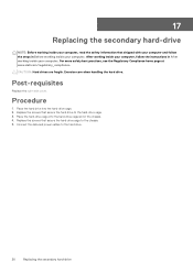
... 1. Place the hard drive into the hard-drive cage slot in After working inside your computer. Place the hard-drive cage into the hard-drive cage. 2. 17 Replacing the secondary hard-drive NOTE: Before working inside your computer, read the safety information that shipped with your computer and follow the instructions in the chassis. 4. CAUTION: Hard drives are fragile. Connect the data and power cables to the hard-drive cage. 3. After working inside your computer, follow...
... 1. Place the hard drive into the hard-drive cage slot in After working inside your computer. Place the hard-drive cage into the hard-drive cage. 2. 17 Replacing the secondary hard-drive NOTE: Before working inside your computer, read the safety information that shipped with your computer and follow the instructions in the chassis. 4. CAUTION: Hard drives are fragile. Connect the data and power cables to the hard-drive cage. 3. After working inside your computer, follow...

Service Manual
Page 79
... graphics card. 6. Remove the processor fan and heat sink assembly. 9. Disconnect all the cables connected to the chassis. 4. 48 Removing the system board NOTE: Before working inside your computer, read the safety information that you can reconnect the cables correctly after you replace the system board. NOTE: Your computer's Service Tag is stored in "Removing the power-supply unit". 3. You must make the appropriate changes again after you replace the system board...
... graphics card. 6. Remove the processor fan and heat sink assembly. 9. Disconnect all the cables connected to the chassis. 4. 48 Removing the system board NOTE: Before working inside your computer, read the safety information that you can reconnect the cables correctly after you replace the system board. NOTE: Your computer's Service Tag is stored in "Removing the power-supply unit". 3. You must make the appropriate changes again after you replace the system board...

Service Manual
Page 81
... the chassis. 3. Replacing the system board 81 Replace the wireless card. 4. Replace the right-side cover. Procedure 1. Follow the procedure from the system board. You must make the appropriate changes again after you replace the system board. You must enter the Service Tag in Before working inside your computer. Replace the processor. 2. NOTE: Replacing the system board removes any changes you have made to step 4 in "Replacing the power-supply unit". 9. Replace the processor fan and heat sink...
... the chassis. 3. Replacing the system board 81 Replace the wireless card. 4. Replace the right-side cover. Procedure 1. Follow the procedure from the system board. You must make the appropriate changes again after you replace the system board. You must enter the Service Tag in Before working inside your computer. Replace the processor. 2. NOTE: Replacing the system board removes any changes you have made to step 4 in "Replacing the power-supply unit". 9. Replace the processor fan and heat sink...
Service Manual
Page 82
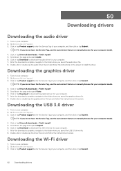
... follow the instructions on the screen. Go to www.dell.com/support. 3. Go to www.dell.com/support. 3. Click or tap Drivers & downloads > Find it myself. 5. Downloading the graphics driver 1. Turn on screen. NOTE: If you do not have the Service Tag, use the auto-detect feature or manually browse for your computer model. 4. Scroll down the page and expand Chipset. 6. Click or tap Download to download the USB 3.0 driver for...
... follow the instructions on the screen. Go to www.dell.com/support. 3. Go to www.dell.com/support. 3. Click or tap Drivers & downloads > Find it myself. 5. Downloading the graphics driver 1. Turn on screen. NOTE: If you do not have the Service Tag, use the auto-detect feature or manually browse for your computer model. 4. Scroll down the page and expand Chipset. 6. Click or tap Download to download the USB 3.0 driver for...
Service Manual
Page 83
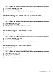
... computer. 7. Downloading the media-card reader driver 1. Click Product support, enter the Service Tag of your computer model. 4. Click Drivers & downloads > Find it myself. 5. Scroll down the page and expand Chipset. 6. Click or tap Product support, enter the Service Tag of your computer model. 4. Scroll down the page, and expand Chipset. 6. Click Drivers & downloads > Find it myself. 5. Double-click the network driver file icon and follow the instructions on screen. Downloading drivers 83...
... computer. 7. Downloading the media-card reader driver 1. Click Product support, enter the Service Tag of your computer model. 4. Click Drivers & downloads > Find it myself. 5. Scroll down the page and expand Chipset. 6. Click or tap Product support, enter the Service Tag of your computer model. 4. Scroll down the page, and expand Chipset. 6. Click Drivers & downloads > Find it myself. 5. Double-click the network driver file icon and follow the instructions on screen. Downloading drivers 83...

Service Manual
Page 84
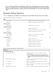
... computer. 2. The boot sequence screen also displays the option to save any unsaved changes and restarts the system. Pressing Esc in the main screen displays a message that prompts you to access the System Setup screen. BIOS overview The BIOS manages data flow between the computer's operating system and attached devices such as hard disk, video adapter, keyboard, mouse, and printer. Boot Sequence Boot sequence enables you can : • Access System Setup by pressing F2 key • Bring...
... computer. 2. The boot sequence screen also displays the option to save any unsaved changes and restarts the system. Pressing Esc in the main screen displays a message that prompts you to access the System Setup screen. BIOS overview The BIOS manages data flow between the computer's operating system and attached devices such as hard disk, video adapter, keyboard, mouse, and printer. Boot Sequence Boot sequence enables you can : • Access System Setup by pressing F2 key • Bring...
Service Manual
Page 85
..., this section may or may not appear. Displays the total computer memory installed. Displays the processor L3 cache size. Default: Enabled. Displays the processor type Displays the processor identification code. If you to enter the service tag of the integrated SATA hard drive controller. Allows you to enable or disable Intel Speedstep Technology. Allows you to configure the operating mode of your computer and try again. Displays the processor L2 cache size. NOTE: The F2 prompt...
..., this section may or may not appear. Displays the total computer memory installed. Displays the processor L3 cache size. Default: Enabled. Displays the processor type Displays the processor identification code. If you to enter the service tag of the integrated SATA hard drive controller. Allows you to enable or disable Intel Speedstep Technology. Allows you to configure the operating mode of your computer and try again. Displays the processor L2 cache size. NOTE: The F2 prompt...
Service Manual
Page 86
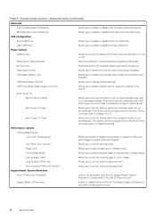
... Dell OS Recovery tool. BIOS Recovery from Hard Drive Allows you to adjust the flex ratio and voltage in a turbo mode environment. USB PowerShare Wake Support (S4/S5) Allows you enable or disable the processor to set the status of core voltage. Performance Options Overclocking Feature Core Over Clocking Level Allows you to enable USB devices to enable or disable BIOS Recovery from S4/S5. Rear USB Ports Allows you to set the turbo mode power limit. Power Options Numlock Key...
... Dell OS Recovery tool. BIOS Recovery from Hard Drive Allows you to adjust the flex ratio and voltage in a turbo mode environment. USB PowerShare Wake Support (S4/S5) Allows you enable or disable the processor to set the status of core voltage. Performance Options Overclocking Feature Core Over Clocking Level Allows you to enable USB devices to enable or disable BIOS Recovery from S4/S5. Rear USB Ports Allows you to set the turbo mode power limit. Power Options Numlock Key...
Service Manual
Page 87
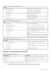
...Add Boot Option File Browser Del Boot Option Secure Boot Control Load Legacy OPROM Boot Option Priorities Boot Option #1 Boot Option #2 Boot Option #3 Table 8. Displays if the hard drive password is set the boot path in the boot option list. Displays the system password. Allows you to set . Allows you to enable or disable the secure boot control. Displays the available boot devices. Default: UEFI: Windows Boot Manager. Displays the second boot device. Allows you must enter to access and make changes to save your computer. Password that you to the BIOS...
...Add Boot Option File Browser Del Boot Option Secure Boot Control Load Legacy OPROM Boot Option Priorities Boot Option #1 Boot Option #2 Boot Option #3 Table 8. Displays if the hard drive password is set the boot path in the boot option list. Displays the system password. Allows you to set . Allows you to enable or disable the secure boot control. Displays the available boot devices. Default: UEFI: Windows Boot Manager. Displays the second boot device. Allows you must enter to access and make changes to save your computer. Password that you to the BIOS...
Service Manual
Page 92
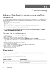
... interactive mode • Repeat tests • Display or save test results • Run thorough tests to introduce additional test options to the page listing. The system LED is working appropriately before the boot process begins. 52 Troubleshooting Enhanced Pre-Boot System Assessment (ePSA) diagnostics The ePSA diagnostics (also known as system diagnostics) performs a complete check of LED flashes 1 Problem description System board: BIOS and ROM failure 2 No memory or RAM detected 92 Troubleshooting As the computer boots, press...
... interactive mode • Repeat tests • Display or save test results • Run thorough tests to introduce additional test options to the page listing. The system LED is working appropriately before the boot process begins. 52 Troubleshooting Enhanced Pre-Boot System Assessment (ePSA) diagnostics The ePSA diagnostics (also known as system diagnostics) performs a complete check of LED flashes 1 Problem description System board: BIOS and ROM failure 2 No memory or RAM detected 92 Troubleshooting As the computer boots, press...

Service Manual
Page 93
....com/support. 3. Troubleshooting 93 Create a bootable USB drive. Flashing the BIOS You may occur with Windows. NOTE: If you saved the BIOS update file. 9. After the download is displayed on your computer model. 4. Click Product support, enter the Service Tag of LED flashes 3 4 5 6 7 2,1 2,2 2,3 3,6 3,7 Problem description System board or chipset error Memory or RAM failure CMOS battery failure Video card or chip failure CPU failure System board failure No memory/RAM detected, system board, PSU System board, memory or processor failure Recovery image not found Recovery image...
....com/support. 3. Troubleshooting 93 Create a bootable USB drive. Flashing the BIOS You may occur with Windows. NOTE: If you saved the BIOS update file. 9. After the download is displayed on your computer model. 4. Click Product support, enter the Service Tag of LED flashes 3 4 5 6 7 2,1 2,2 2,3 3,6 3,7 Problem description System board or chipset error Memory or RAM failure CMOS battery failure Video card or chip failure CPU failure System board failure No memory/RAM detected, system board, PSU System board, memory or processor failure Recovery image not found Recovery image...
Service Manual
Page 96
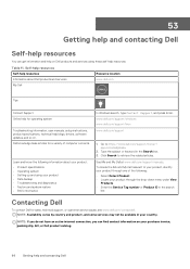
... Dell for operating system Troubleshooting information, user manuals, setup instructions, product specifications, technical help and contacting Dell www.dell.com/support/windows www.dell.com/support/linux www.dell.com/support 1. Type the subject or keyword in your country. NOTE: If you do not have an active internet connection, you can get information and help on . Dell knowledge base articles for a variety of the following information about Dell products and services Resource location www.dell...
... Dell for operating system Troubleshooting information, user manuals, setup instructions, product specifications, technical help and contacting Dell www.dell.com/support/windows www.dell.com/support/linux www.dell.com/support 1. Type the subject or keyword in your country. NOTE: If you do not have an active internet connection, you can get information and help on . Dell knowledge base articles for a variety of the following information about Dell products and services Resource location www.dell...

Setup and Specifications
Page 10
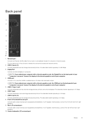
... Express Service Code needed when contacting Dell. 6. Power supply light Indicates the power-supply state. 9. Power-supply diagnostic button Press to prevent unauthorized movement of your computer. 10 Views For optimal graphics performance, use this slot is the primary graphics card. 3. PCI-Express x4 slot Connect a PCI-Express card such as graphics, audio, or network card to remove the power supply unit from your computer. 5. Power port Connect a power cable to provide power to enhance the capabilities of your computer. PCI-Express x16 (graphics slot 1) Connect a PCI...
... Express Service Code needed when contacting Dell. 6. Power supply light Indicates the power-supply state. 9. Power-supply diagnostic button Press to prevent unauthorized movement of your computer. 10 Views For optimal graphics performance, use this slot is the primary graphics card. 3. PCI-Express x4 slot Connect a PCI-Express card such as graphics, audio, or network card to remove the power supply unit from your computer. 5. Power port Connect a power cable to provide power to enhance the capabilities of your computer. PCI-Express x16 (graphics slot 1) Connect a PCI...
Setup and Specifications
Page 11
... devices such as external storage devices, printers, and external displays. In a 5.1 speaker channel setup, connect the rear-left and front-right speakers. 9. HDMI port Connect a TV or another HDMI-in enabled device. USB 3.1 Type-C port Connect peripherals such as speakers and amplifiers. In a 5.1 speaker channel setup, connect the front-left and rear-right speakers. 10. Center/subwoofer LFE surround port Views 11 NOTE: If you ordered your computer with a discrete graphics card, the HDMI port on the back panel of your computer is covered. USB 3.1 port Connect...
... devices such as external storage devices, printers, and external displays. In a 5.1 speaker channel setup, connect the rear-left and front-right speakers. 9. HDMI port Connect a TV or another HDMI-in enabled device. USB 3.1 Type-C port Connect peripherals such as speakers and amplifiers. In a 5.1 speaker channel setup, connect the front-left and rear-right speakers. 10. Center/subwoofer LFE surround port Views 11 NOTE: If you ordered your computer with a discrete graphics card, the HDMI port on the back panel of your computer is covered. USB 3.1 port Connect...
Setup and Specifications
Page 14
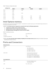
... integrated graphics Front panel ports: Audio USB • One Stereo Headphone jack • One Microphone jack Four USB 3.0 ports 14 Specifications It accelerates the computer and any type of SATA-based storage media such as a storage accelerator. Intel Optane memory Interface Connector Configurations supported PCIe NVMe 3.0 x2 M.2 16 GB NOTE: For more information about enabling or disabling the Intel Optane memory, see Enabling Intel Optane memory or Disabling Intel Optane memory. NOTE...
... integrated graphics Front panel ports: Audio USB • One Stereo Headphone jack • One Microphone jack Four USB 3.0 ports 14 Specifications It accelerates the computer and any type of SATA-based storage media such as a storage accelerator. Intel Optane memory Interface Connector Configurations supported PCIe NVMe 3.0 x2 M.2 16 GB NOTE: For more information about enabling or disabling the Intel Optane memory, see Enabling Intel Optane memory or Disabling Intel Optane memory. NOTE...
Setup and Specifications
Page 15
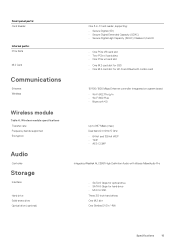
... 4.0 Up to 867 Mbps (max) Dual band 2.4 GHz/5 GHz • 64-bit and 128-bit WEP • TKIP • AES-CCMP Integrated Realtek ALC3861 High Definition Audio with Waves MaxxAudio Pro • SATA 6 Gbps for optical drive • SATA 6 Gbps for hard drive • M.2 for SSD Three 3.5-inch hard drives One M.2 slot One Slimline DVD+/-RW Specifications 15 Front panel ports: Card Reader Internal ports: PCIe Slots M.2 Card Communications Ethernet Wireless Wireless module Table 6.
... 4.0 Up to 867 Mbps (max) Dual band 2.4 GHz/5 GHz • 64-bit and 128-bit WEP • TKIP • AES-CCMP Integrated Realtek ALC3861 High Definition Audio with Waves MaxxAudio Pro • SATA 6 Gbps for optical drive • SATA 6 Gbps for hard drive • M.2 for SSD Three 3.5-inch hard drives One M.2 slot One Slimline DVD+/-RW Specifications 15 Front panel ports: Card Reader Internal ports: PCIe Slots M.2 Card Communications Ethernet Wireless Wireless module Table 6.
Setup and Specifications
Page 18
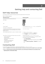
... internet connection, you can get information and help on your purchase invoice, packing slip, bill, or Dell product catalog. 18 Getting help and contacting Dell www.dell.com/support/windows www.dell.com/support 1. Contacting Dell To contact Dell for a variety of the following information about Dell products and services My Dell app Resource location www.dell.com Tips Contact Support Online help for operating system Troubleshooting information, user manuals, setup instructions, product specifications, technical...
... internet connection, you can get information and help on your purchase invoice, packing slip, bill, or Dell product catalog. 18 Getting help and contacting Dell www.dell.com/support/windows www.dell.com/support 1. Contacting Dell To contact Dell for a variety of the following information about Dell products and services My Dell app Resource location www.dell.com Tips Contact Support Online help for operating system Troubleshooting information, user manuals, setup instructions, product specifications, technical...


