
Owner's Manual
Page 119
...in this section, follow the safety instructions in to the computer. 11 Connect your computer and devices to avoid blocking airflow between the fan and cooling vents. 9 Replace the drive panel (see "Replacing the Drive Panel" on page 114). 10 Replace the computer cover (see "Replacing the Computer.... 12 Enter system setup (see "Removing the Drive Panel" on page 113). 4 Disconnect the power and data cables from the back of the Media Card Reader. Removing and Installing Parts 119 8 Check all cable connections and fold cables out of the way to their electrical outlets, and turn them on.
...in this section, follow the safety instructions in to the computer. 11 Connect your computer and devices to avoid blocking airflow between the fan and cooling vents. 9 Replace the drive panel (see "Replacing the Drive Panel" on page 114). 10 Replace the computer cover (see "Replacing the Computer.... 12 Enter system setup (see "Removing the Drive Panel" on page 113). 4 Disconnect the power and data cables from the back of the Media Card Reader. Removing and Installing Parts 119 8 Check all cable connections and fold cables out of the way to their electrical outlets, and turn them on.

Owner's Manual
Page 123
... and Installing Parts 123 Removing an Optical Drive 1 Follow the procedures in this time, disconnect the data cable from the back of the way to avoid blocking airflow between the fan and cooling vents. 9 Replace the drive panel (see "Replacing the Drive Panel" on page 114). 10 Replace the...see "Removing the Computer Cover" on page 86). 3 Remove the drive panel (see "Removing the Drive Panel" on page 113). 4 Disconnect the power and data cables from the system board and set it aside. NOTE: If you begin any software required for drive operation. 12 Enter system setup (see "Replacing...
... and Installing Parts 123 Removing an Optical Drive 1 Follow the procedures in this time, disconnect the data cable from the back of the way to avoid blocking airflow between the fan and cooling vents. 9 Replace the drive panel (see "Replacing the Drive Panel" on page 114). 10 Replace the...see "Removing the Computer Cover" on page 86). 3 Remove the drive panel (see "Removing the Drive Panel" on page 113). 4 Disconnect the power and data cables from the system board and set it aside. NOTE: If you begin any software required for drive operation. 12 Enter system setup (see "Replacing...
Owner's Manual
Page 127
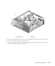
... turn them on. To locate the system board connector, see "System Board Components" on page 89. 1 2 1 power cable 2 data cable 9 Check all cable connections and fold cables out of the way to avoid blocking airflow between the fan and cooling vents. 10 Replace the drive panel (see "Replacing the Drive Panel" on page 114). 11 Replace...
... turn them on. To locate the system board connector, see "System Board Components" on page 89. 1 2 1 power cable 2 data cable 9 Check all cable connections and fold cables out of the way to avoid blocking airflow between the fan and cooling vents. 10 Replace the drive panel (see "Replacing the Drive Panel" on page 114). 11 Replace...
Owner's Manual
Page 128
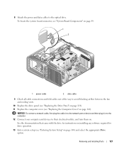
... the coolant, wash your skin with your eyes immediately with water, with soap and water. Removing the Liquid Cooling Assembly 1 Follow the procedures in "Before You Begin" on page 85. 2 Remove the computer cover (see...of eye contact with the coolant, rinse your eyelids open, for Liquid Cooling Assembly • The liquid cooling assembly is not necessary to disconnect the optical drive cables unless you touch it. 3 Remove the drive panel (see "Removing ... to fully remove the optical drive(s) from the power outlet and contact Dell Technical Support. • In the event of the way.
... the coolant, wash your skin with your eyes immediately with water, with soap and water. Removing the Liquid Cooling Assembly 1 Follow the procedures in "Before You Begin" on page 85. 2 Remove the computer cover (see...of eye contact with the coolant, rinse your eyelids open, for Liquid Cooling Assembly • The liquid cooling assembly is not necessary to disconnect the optical drive cables unless you touch it. 3 Remove the drive panel (see "Removing ... to fully remove the optical drive(s) from the power outlet and contact Dell Technical Support. • In the event of the way.
Owner's Manual
Page 129
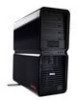
Removing and Installing Parts 129 1 2 1 drive release latch 2 optical drive 5 Remove any full-length expansion cards (see "Removing PCI and PCI Express Cards" on page 95). 6 Disconnect the liquid cooling assembly power cable. 7 Disconnect the liquid cooling assembly cable from the TEC_PUMP connector on the system board (see "System Board Components" on page 89).
Removing and Installing Parts 129 1 2 1 drive release latch 2 optical drive 5 Remove any full-length expansion cards (see "Removing PCI and PCI Express Cards" on page 95). 6 Disconnect the liquid cooling assembly power cable. 7 Disconnect the liquid cooling assembly cable from the TEC_PUMP connector on the system board (see "System Board Components" on page 89).
Owner's Manual
Page 130
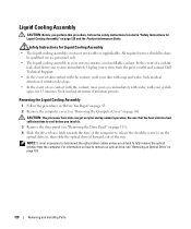
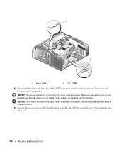
1 2 1 power cable 2 TEC_PUMP 8 Disconnect the fan cable from the FAN1_CPU connector on the system board (see "System Board Components" on its side to the liquid cooling assembly. When you remove the liquid cooling assembly, lay it upside down or on page 89). NOTICE: The screw at the front of the... Remove the screw and set it aside in a secure location. 9 Loosen the seven screws on the liquid cooling assembly, then lift the assembly out of the liquid cooling assembly is attached to avoid damaging the heatsink thermal interface. NOTICE: The processor heat sink is not captive....
1 2 1 power cable 2 TEC_PUMP 8 Disconnect the fan cable from the FAN1_CPU connector on the system board (see "System Board Components" on its side to the liquid cooling assembly. When you remove the liquid cooling assembly, lay it upside down or on page 89). NOTICE: The screw at the front of the... Remove the screw and set it aside in a secure location. 9 Loosen the seven screws on the liquid cooling assembly, then lift the assembly out of the liquid cooling assembly is attached to avoid damaging the heatsink thermal interface. NOTICE: The processor heat sink is not captive....
Owner's Manual
Page 131
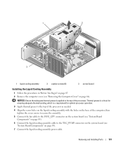
..."Before You Begin" on page 85. 2 Remove the computer cover (see "System Board Components" on page 89). 7 Connect the liquid cooling assembly power cable. NOTICE: Ensure that adequate thermal grease is a requirement for ensuring adequate thermal bonding, which is applied to the top of the computer, then...the system board (see "System Board Components" on page 89). 6 Connect the liquid cooling assembly cable to the top of the processor as needed. 4 Align the screw holes on the liquid cooling assembly with the holes on page 86). Thermal grease is critical for optimal processor operation...
..."Before You Begin" on page 85. 2 Remove the computer cover (see "System Board Components" on page 89). 7 Connect the liquid cooling assembly power cable. NOTICE: Ensure that adequate thermal grease is a requirement for ensuring adequate thermal bonding, which is applied to the top of the computer, then...the system board (see "System Board Components" on page 89). 6 Connect the liquid cooling assembly cable to the top of the processor as needed. 4 Align the screw holes on the liquid cooling assembly with the holes on page 86). Thermal grease is critical for optimal processor operation...

Owner's Manual
Page 132
...the computer cover (see "Removing the Computer Cover" on page 86). 3 Disconnect the power cables from the POWER1 and POWER2 connectors (see "System Board Components" on page 89) on the system board. 4 Remove the liquid cooling assembly (see "Replacing the Computer Cover" on page 160). 8 Gently slide the optical...unless you removed (see "Installing PCI and PCI Express Cards" on page 97). 11 Close the computer cover (see "Removing the Liquid Cooling Assembly" on page 128). 5 Push down and out on . Performing these steps incorrectly could damage your computer and devices to electrical outlets...
...the computer cover (see "Removing the Computer Cover" on page 86). 3 Disconnect the power cables from the POWER1 and POWER2 connectors (see "System Board Components" on page 89) on the system board. 4 Remove the liquid cooling assembly (see "Replacing the Computer Cover" on page 160). 8 Gently slide the optical...unless you removed (see "Installing PCI and PCI Express Cards" on page 97). 11 Close the computer cover (see "Removing the Liquid Cooling Assembly" on page 128). 5 Push down and out on . Performing these steps incorrectly could damage your computer and devices to electrical outlets...

Owner's Manual
Page 134
... and POWER2 connectors (see "System Board Components" on page 89) on the system board. 9 Close the computer cover (see "Installing the Liquid Cooling Assembly" on page 131). 8 Reconnect the power cables to touch or bend the pins on . 134 Removing and Installing Parts When the processor is positioned correctly, press it with the...
... and POWER2 connectors (see "System Board Components" on page 89) on the system board. 9 Close the computer cover (see "Installing the Liquid Cooling Assembly" on page 131). 8 Reconnect the power cables to touch or bend the pins on . 134 Removing and Installing Parts When the processor is positioned correctly, press it with the...


