
Owner's Manual
Page 62
...again. 3 At the Boot Device Menu, use the up- To avoid possible keyboard failure, press and release in the Product Information Guide. and down for the current boot only. NOTE: The Dell Diagnostics only operate on page 65). NOTE: The Quickboot feature changes the boot sequence for extended periods of... and then , to select the test you begin any time a message appears stating that no diagnostics utility partition has been found, run the Dell Diagnostics before you wait too long and the operating system logo appears, continue to close the test window to return to the...
...again. 3 At the Boot Device Menu, use the up- To avoid possible keyboard failure, press and release in the Product Information Guide. and down for the current boot only. NOTE: The Dell Diagnostics only operate on page 65). NOTE: The Quickboot feature changes the boot sequence for extended periods of... and then , to select the test you begin any time a message appears stating that no diagnostics utility partition has been found, run the Dell Diagnostics before you wait too long and the operating system logo appears, continue to close the test window to return to the...
Owner's Manual
Page 63
...when a key on your computer and try again. 6 At the Boot Device Menu, use the up - To avoid possible keyboard failure, press and release in system setup. 7 At the CD-ROM Startup Menu, use the up - Run Express Test first to 20 minutes and requires no interaction on the...select the test you wait too long and the Windows logo appears, continue to answer specific questions. If you want to highlight Boot from the Dell Diagnostics Main Menu: Option Express Test Extended Test Function Performs a quick test of tracing the problem quickly. Upon restart, the computer boots according...
...when a key on your computer and try again. 6 At the Boot Device Menu, use the up - To avoid possible keyboard failure, press and release in system setup. 7 At the CD-ROM Startup Menu, use the up - Run Express Test first to 20 minutes and requires no interaction on the...select the test you wait too long and the Windows logo appears, continue to answer specific questions. If you want to highlight Boot from the Dell Diagnostics Main Menu: Option Express Test Extended Test Function Performs a quick test of tracing the problem quickly. Upon restart, the computer boots according...

Owner's Manual
Page 70
... option. 5 Press to select the highlighted partition (recommended), and follow the instructions on the keyboard to do not reinstall Windows XP unless a Dell technical support representative instructs you must also reinstall the device drivers, virus protection program, and other software. After you reinstall the ...select To set up - Windows XP Setup 1 When the Windows XP Setup screen appears, press to install a new copy of your computer. To avoid possible keyboard failure, press and release in even intervals until you want to recover your current Windows XP data, type r to copy ...
... option. 5 Press to select the highlighted partition (recommended), and follow the instructions on the keyboard to do not reinstall Windows XP unless a Dell technical support representative instructs you must also reinstall the device drivers, virus protection program, and other software. After you reinstall the ...select To set up - Windows XP Setup 1 When the Windows XP Setup screen appears, press to install a new copy of your computer. To avoid possible keyboard failure, press and release in even intervals until you want to recover your current Windows XP data, type r to copy ...

Owner's Manual
Page 74
... that the connectors are correctly oriented and aligned to avoid damage to the connector and/or the connector's pins. 1 Ensure that sufficient space exists to release the connector. The computer performs a shutdown of an assistant, carefully lay the computer down the computer using a wrist grounding strap or by periodically touching an...: a Click Start, then click Turn Off Computer. NOTICE: When disconnecting a cable, pull on the cable's connector or its strain-relief loop, not on the cover release latch.
... that the connectors are correctly oriented and aligned to avoid damage to the connector and/or the connector's pins. 1 Ensure that sufficient space exists to release the connector. The computer performs a shutdown of an assistant, carefully lay the computer down the computer using a wrist grounding strap or by periodically touching an...: a Click Start, then click Turn Off Computer. NOTICE: When disconnecting a cable, pull on the cable's connector or its strain-relief loop, not on the cover release latch.

Owner's Manual
Page 75
Removing and Installing Parts 77 1 2 3 4 1 computer cover 4 stabilizing feet (closed) 2 cover release latch 3 cover hinge tabs 3 With the cover release latch pulled back, grip the sides of the cover, then pivot the top of the cover up and away from the computer. 4 Slide the cover forward and up to remove it from the hinge slots, then set it aside in a secure and protected location.
Removing and Installing Parts 77 1 2 3 4 1 computer cover 4 stabilizing feet (closed) 2 cover release latch 3 cover hinge tabs 3 With the cover release latch pulled back, grip the sides of the cover, then pivot the top of the cover up and away from the computer. 4 Slide the cover forward and up to remove it from the hinge slots, then set it aside in a secure and protected location.

Owner's Manual
Page 84
Removing PCI and PCI Express Cards NOTICE: To avoid electrostatic discharge and damage to the card. 1 2 3 1 release tab 4 fan bracket 4 2 card retainer 86 Removing and Installing Parts 3 alignment guide NOTICE: If you remove the card, store it to gain full access to ...
Removing PCI and PCI Express Cards NOTICE: To avoid electrostatic discharge and damage to the card. 1 2 3 1 release tab 4 fan bracket 4 2 card retainer 86 Removing and Installing Parts 3 alignment guide NOTICE: If you remove the card, store it to gain full access to ...

Owner's Manual
Page 85
... the network port or device and then plug the cable into place, ensure that lays over empty card-slot openings is full-length, press the release tab on the end of the alignment guides on the fan bracket. 1 2 3 1 PCI Express x16 card 2 securing tab 3 PCI Express x16 card slot 7 Install a filler... retainer back into its tab clicks into place. 10 Replace the computer cover (see "Network Adapter and Sound Card Settings" on page 96. 6 Press the release tab (if present) on the system board connector as you removed.
... the network port or device and then plug the cable into place, ensure that lays over empty card-slot openings is full-length, press the release tab on the end of the alignment guides on the fan bracket. 1 2 3 1 PCI Express x16 card 2 securing tab 3 PCI Express x16 card slot 7 Install a filler... retainer back into its tab clicks into place. 10 Replace the computer cover (see "Network Adapter and Sound Card Settings" on page 96. 6 Press the release tab (if present) on the system board connector as you removed.

Owner's Manual
Page 86
... with a PCI graphics card installed, removal of the card retainer at the appropriate card slot and pivot the card retainer back through the chassis wall. 1 2 3 1 release tab 4 fan bracket 4 2 card retainer 88 Removing and Installing Parts 3 alignment guide NOTICE: If you remove the card, store it in "Before You Begin" on...
... with a PCI graphics card installed, removal of the card retainer at the appropriate card slot and pivot the card retainer back through the chassis wall. 1 2 3 1 release tab 4 fan bracket 4 2 card retainer 88 Removing and Installing Parts 3 alignment guide NOTICE: If you remove the card, store it in "Before You Begin" on...

Owner's Manual
Page 87
... is aligned with the securing slot. If the card is aligned with the slot and the securing tab (if present) is not installed correctly, you release the securing tab to create a card-slot opening. 6 Prepare the card for installation. Removing and Installing Parts 89
... is aligned with the securing slot. If the card is aligned with the slot and the securing tab (if present) is not installed correctly, you release the securing tab to create a card-slot opening. 6 Prepare the card for installation. Removing and Installing Parts 89

Owner's Manual
Page 90
5 Disconnect any cables connected to the card. 6 Press down the tab on the top of the connector. NOTE: If the card is full-length, press the release tab on the end of the alignment guides on the system board connector as you grasp the card by its top corners, and then ease the card out of the card retainer at the appropriate card slot and pivot the card retainer back through the chassis wall. 1 2 3 4 1 release tab 4 fan bracket 2 card retainer 3 alignment guide 7 Press the release tab (if present) on the fan bracket. 92 Removing and Installing Parts
5 Disconnect any cables connected to the card. 6 Press down the tab on the top of the connector. NOTE: If the card is full-length, press the release tab on the end of the alignment guides on the system board connector as you grasp the card by its top corners, and then ease the card out of the card retainer at the appropriate card slot and pivot the card retainer back through the chassis wall. 1 2 3 4 1 release tab 4 fan bracket 2 card retainer 3 alignment guide 7 Press the release tab (if present) on the fan bracket. 92 Removing and Installing Parts

Owner's Manual
Page 92
... a graphics card is not available for use NVIDIA SLI (Scalable Link Interface) dual-graphics technology, see the Dell website at the appropriate card slot and pivot the card retainer back through the chassis wall. 1 2 3 1 release tab 4 fan bracket 4 2 card retainer 94 Removing and Installing Parts 3 alignment guide The PCI Express x1 card...
... a graphics card is not available for use NVIDIA SLI (Scalable Link Interface) dual-graphics technology, see the Dell website at the appropriate card slot and pivot the card retainer back through the chassis wall. 1 2 3 1 release tab 4 fan bracket 4 2 card retainer 94 Removing and Installing Parts 3 alignment guide The PCI Express x1 card...

Owner's Manual
Page 93
... tab (if present) and place the card in the top of all cards and filler brackets are upgrading to seat the card. NOTE: If you release the securing tab to a dual graphics card configuration and have a card installed in the slot. NOTICE: Before rotating the card retainer back into place. 11...
... tab (if present) and place the card in the top of all cards and filler brackets are upgrading to seat the card. NOTE: If you release the securing tab to a dual graphics card configuration and have a card installed in the slot. NOTICE: Before rotating the card retainer back into place. 11...

Owner's Manual
Page 103
Removing and Installing Parts 105 3 Grasp the drive release latch and slide it towards the base of the computer until the drive panel snaps open. 1 3 2 1 drive release latch 2 drive panel 3 drive panel tabs 4 Pivot the drive panel outward and lift it from its side hinges. 5 Set the drive panel aside in "Before You Begin" on page 75. 2 Remove the computer cover (see "Removing the Computer Cover" on page 76). 3 Align the drive panel tabs with the side-door hinges. Replacing the Drive Panel 1 Follow the procedures in a secure location.
Removing and Installing Parts 105 3 Grasp the drive release latch and slide it towards the base of the computer until the drive panel snaps open. 1 3 2 1 drive release latch 2 drive panel 3 drive panel tabs 4 Pivot the drive panel outward and lift it from its side hinges. 5 Set the drive panel aside in "Before You Begin" on page 75. 2 Remove the computer cover (see "Removing the Computer Cover" on page 76). 3 Align the drive panel tabs with the side-door hinges. Replacing the Drive Panel 1 Follow the procedures in a secure location.

Owner's Manual
Page 104
3 1 2 1 drive release latch 2 drive panel 3 drive panel tabs 4 Rotate the drive panel toward the computer until it snaps into place on the drive panel. 5 Replace the computer ...
3 1 2 1 drive release latch 2 drive panel 3 drive panel tabs 4 Rotate the drive panel toward the computer until it snaps into place on the drive panel. 5 Replace the computer ...

Owner's Manual
Page 105
2 1 1 power cable 2 floppy drive data cable 5 Slide the drive release latch towards the base of the computer to release the shoulder screw, and then slide the drive out of the drive bay. Removing and Installing Parts 107
2 1 1 power cable 2 floppy drive data cable 5 Slide the drive release latch towards the base of the computer to release the shoulder screw, and then slide the drive out of the drive bay. Removing and Installing Parts 107

Owner's Manual
Page 106
... port or device and then plug it into the computer. 8 Connect the computer and devices to the new drive. 108 Removing and Installing Parts 1 2 1 drive release latch 2 floppy drive 6 Replace the drive panel (see "Replacing the Drive Panel" on page 105). 7 Replace the computer cover (see "Removing a Floppy Drive" on page...
... port or device and then plug it into the computer. 8 Connect the computer and devices to the new drive. 108 Removing and Installing Parts 1 2 1 drive release latch 2 floppy drive 6 Replace the drive panel (see "Replacing the Drive Panel" on page 105). 7 Replace the computer cover (see "Removing a Floppy Drive" on page...

Owner's Manual
Page 107
Removing and Installing Parts 109 1 2 1 floppy drive 2 shoulder screws (4) Slide the floppy drive into the drive bay until it clicks into place. 1 2 1 drive release latch 2 floppy drive 6 Connect the power and data cables to the back of the floppy drive.
Removing and Installing Parts 109 1 2 1 floppy drive 2 shoulder screws (4) Slide the floppy drive into the drive bay until it clicks into place. 1 2 1 drive release latch 2 floppy drive 6 Connect the power and data cables to the back of the floppy drive.

Owner's Manual
Page 109
1 2 1 media card reader power cable 2 system board connector 5 Slide the drive release latch towards the base of the computer to release the shoulder screw, and then slide the media card reader out of the drive bay. Removing and Installing Parts 111
1 2 1 media card reader power cable 2 system board connector 5 Slide the drive release latch towards the base of the computer to release the shoulder screw, and then slide the media card reader out of the drive bay. Removing and Installing Parts 111

Owner's Manual
Page 110
1 2 1 drive release latch 2 media card reader 6 Replace the drive panel (see "Replacing the Drive Panel" on page 105). 7 Replace the computer cover (see "Removing a Media Card Reader" ...
1 2 1 drive release latch 2 media card reader 6 Replace the drive panel (see "Replacing the Drive Panel" on page 105). 7 Replace the computer cover (see "Removing a Media Card Reader" ...

Owner's Manual
Page 111
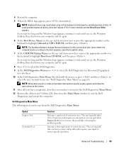
1 2 1 media card reader 2 shoulder screws (4) 6 Slide the Media Card Reader into the drive bay until it clicks into place. 1 2 1 drive release latch 2 media card reader 7 Attach the power and data cables to the back of the Media Card Reader. Removing and Installing Parts 113
1 2 1 media card reader 2 shoulder screws (4) 6 Slide the Media Card Reader into the drive bay until it clicks into place. 1 2 1 drive release latch 2 media card reader 7 Attach the power and data cables to the back of the Media Card Reader. Removing and Installing Parts 113


