Owner's Manual
Page 70
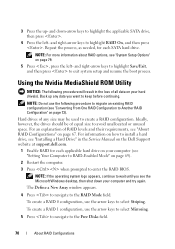
.... Back up - For information on how to install a hard drive, see the Microsoft Windows desktop, then shut down -arrow keys to highlight the applicable SATA drive, then press . 4 Press the left - To create a RAID 0 configuration, use the arrow keys to select Mirroring. 5 Press to navigate to... website at support.dell.com. 1 Enable RAID for each applicable hard drive on your computer (see "About RAID Configurations" on page 79. 5 Press , press the left - Repeat the process, as needed, for each SATA hard drive. Ideally, however, the drives should be used to RAID-Enabled Mode" on...
.... Back up - For information on how to install a hard drive, see the Microsoft Windows desktop, then shut down -arrow keys to highlight the applicable SATA drive, then press . 4 Press the left - To create a RAID 0 configuration, use the arrow keys to select Mirroring. 5 Press to navigate to... website at support.dell.com. 1 Enable RAID for each applicable hard drive on your computer (see "About RAID Configurations" on page 79. 5 Press , press the left - Repeat the process, as needed, for each SATA hard drive. Ideally, however, the drives should be used to RAID-Enabled Mode" on...
Owner's Manual
Page 80
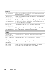
... or disables a user to define or change any values related Configuration to IDE or SATA devices such as hard drives, optical drives, and so on your system. Overclock This option enables you to set a user password. Password Set User Password ...
... or disables a user to define or change any values related Configuration to IDE or SATA devices such as hard drives, optical drives, and so on your system. Overclock This option enables you to set a user password. Password Set User Password ...
Owner's Manual
Page 145
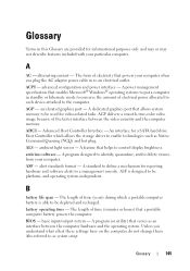
... between the video circuitry and the computer memory. BIOS - A program (or utility) that a portable computer battery powers the computer. Also referred to be used for a SATA hard drive Host Controller which a portable computer battery is designed to be depleted and recharged. AGP - ALS - antivirus software - The length of time (years) during...
... between the video circuitry and the computer memory. BIOS - A program (or utility) that a portable computer battery powers the computer. Also referred to be used for a SATA hard drive Host Controller which a portable computer battery is designed to be depleted and recharged. AGP - ALS - antivirus software - The length of time (years) during...
Owner's Manual
Page 156
... and light. radio frequency interference - revolutions per minute. A jumper on the system board of the SCSI interface (as hard drives, CD drives, printers, and scanners. SATA - A high-speed interface used for errors. Data and/or files you shut down the computer. A faster, serial version of some computers that cannot be seen...
... and light. radio frequency interference - revolutions per minute. A jumper on the system board of the SCSI interface (as hard drives, CD drives, printers, and scanners. SATA - A high-speed interface used for errors. Data and/or files you shut down the computer. A faster, serial version of some computers that cannot be seen...
Service Manual
Page 3
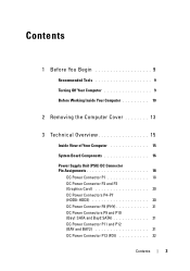
... P3 (Graphics Card 20 DC Power Connectors P4-P7 (HDD0-HDD3 20 DC Power Connector P8 (PHY 21 DC Power Connectors P9 and P10 (Bay1 SATA and Bay2 SATA 21 DC Power Connector P11 and P12 (BAY and BAY2 21 DC Power Connector P13 (FDI 22 Contents 3
... P3 (Graphics Card 20 DC Power Connectors P4-P7 (HDD0-HDD3 20 DC Power Connector P8 (PHY 21 DC Power Connectors P9 and P10 (Bay1 SATA and Bay2 SATA 21 DC Power Connector P11 and P12 (BAY and BAY2 21 DC Power Connector P13 (FDI 22 Contents 3
Service Manual
Page 4
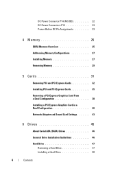
... From a Dual Configuration 38 Installing a PCI Express Graphics Card in a Dual Configuration 40 Network Adapter and Sound Card Settings 43 6 Drives 45 About Serial ATA (SATA) Drives 46 General Drive Installation Guidelines 46 Hard Drive 47 Removing a Hard Drive 47 Installing a Hard Drive 50 4 Contents
... From a Dual Configuration 38 Installing a PCI Express Graphics Card in a Dual Configuration 40 Network Adapter and Sound Card Settings 43 6 Drives 45 About Serial ATA (SATA) Drives 46 General Drive Installation Guidelines 46 Hard Drive 47 Removing a Hard Drive 47 Installing a Hard Drive 50 4 Contents
Service Manual
Page 7
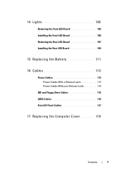
14 Lights 105 Removing the Front LED Board 105 Installing the Front LED Board 106 Removing the Rear LED Board 107 Installing the Rear LED Board 109 15 Replacing the Battery 111 16 Cables 113 Power Cables 113 Power Cables With a Release Latch 113 Power Cables Without a Release Latch 114 IDE and Floppy-Drive Cables 115 SATA Cables 116 Front I/O Panel Cables 117 17 Replacing the Computer Cover 119 Contents 7
14 Lights 105 Removing the Front LED Board 105 Installing the Front LED Board 106 Removing the Rear LED Board 107 Installing the Rear LED Board 109 15 Replacing the Battery 111 16 Cables 113 Power Cables 113 Power Cables With a Release Latch 113 Power Cables Without a Release Latch 114 IDE and Floppy-Drive Cables 115 SATA Cables 116 Front I/O Panel Cables 117 17 Replacing the Computer Cover 119 Contents 7
Service Manual
Page 17
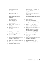
... memory module connectors (DIMM2 and DIMM 3) (DIMM0 and DIMM1) 23 main power connector (POWER) 24 IDE drive connector (IDE) 25 North bridge fan connector 26 SATA connectors (SATA0-3) 27 battery socket (BATTERY) Technical Overview 17
... memory module connectors (DIMM2 and DIMM 3) (DIMM0 and DIMM1) 23 main power connector (POWER) 24 IDE drive connector (IDE) 25 North bridge fan connector 26 SATA connectors (SATA0-3) 27 battery socket (BATTERY) Technical Overview 17

Service Manual
Page 21
DC Power Connector P8 (PHY) Pin Number 1 2 3 4 1234 Signal name +12 VB DC COM COM +5 VDC 18-AWG Wire Color White Black Black Red DC Power Connectors P9 and P10 (Bay1 SATA and Bay2 SATA) 5 432 1 Pin Number 1 2 3 4 5 Signal name +3.3 VDC COM +5 VDC COM +12 VC DC 18-AWG Wire Color Orange Black Red Black Blue/White DC Power Connector P11 and P12 (BAY and BAY2) 1234 Technical Overview 21
DC Power Connector P8 (PHY) Pin Number 1 2 3 4 1234 Signal name +12 VB DC COM COM +5 VDC 18-AWG Wire Color White Black Black Red DC Power Connectors P9 and P10 (Bay1 SATA and Bay2 SATA) 5 432 1 Pin Number 1 2 3 4 5 Signal name +3.3 VDC COM +5 VDC COM +12 VC DC 18-AWG Wire Color Orange Black Red Black Blue/White DC Power Connector P11 and P12 (BAY and BAY2) 1234 Technical Overview 21

Service Manual
Page 45
Drives Your computer supports: • Four SATA devices (hard drives or optical drives) • One IDE device (one hard drive or one optical drive) • One floppy drive or one media card reader NOTICE: When removing and replacing drives, be sure to leave the drive data and power cables connected to the system board. NOTE: The 3.5-inch media card reader/floppy drive carrier is not interchangeable with the hard drive carrier. 1 2 1 CD/DVD drive bays (2) 3 hard-drive bays (4) 3 2 floppy drive/media card reader Drives 45
Drives Your computer supports: • Four SATA devices (hard drives or optical drives) • One IDE device (one hard drive or one optical drive) • One floppy drive or one media card reader NOTICE: When removing and replacing drives, be sure to leave the drive data and power cables connected to the system board. NOTE: The 3.5-inch media card reader/floppy drive carrier is not interchangeable with the hard drive carrier. 1 2 1 CD/DVD drive bays (2) 3 hard-drive bays (4) 3 2 floppy drive/media card reader Drives 45

Service Manual
Page 46
... hard drive, allowing for the cable select setting, the device attached to four serial ATA hard drives and two serial ATA optical drives. SATA drives provide the following benefits by the connector at each end and press firmly into the connector. When connecting... a SATA cable, hold the cable by the connector at each end and pull until the connector detaches. 1 3 2 1 SATA data cable 3 SATA drive 2 SATA data connector (on the system board) When you connect two IDE devices to the connectors...
... hard drive, allowing for the cable select setting, the device attached to four serial ATA hard drives and two serial ATA optical drives. SATA drives provide the following benefits by the connector at each end and press firmly into the connector. When connecting... a SATA cable, hold the cable by the connector at each end and pull until the connector detaches. 1 3 2 1 SATA data cable 3 SATA drive 2 SATA data connector (on the system board) When you connect two IDE devices to the connectors...

Service Manual
Page 48
1 2 3 1 SATA power cable 2 3 SATA data connector (on the system board) SATA data cable 4 Press the black tabs on each side of the hard-drive bracket towards each other and slide the drive up and out of the hard-drive bay. 48 Drives
1 2 3 1 SATA power cable 2 3 SATA data connector (on the system board) SATA data cable 4 Press the black tabs on each side of the hard-drive bracket towards each other and slide the drive up and out of the hard-drive bay. 48 Drives

Service Manual
Page 52
1 2 3 1 SATA power cable 3 SATA data connector (on the system board) 2 SATA data cable 8 Replace the computer cover (see "Replacing the Computer Cover" on installing any software required for instructions on page 119). See the documentation that came with the drive for drive operation. 52 Drives NOTICE: To connect a network cable, first plug the cable into the network port or device and then plug it into the computer. 9 Connect your computer and devices to electrical outlets, and then turn them on.
1 2 3 1 SATA power cable 3 SATA data connector (on the system board) 2 SATA data cable 8 Replace the computer cover (see "Replacing the Computer Cover" on installing any software required for instructions on page 119). See the documentation that came with the drive for drive operation. 52 Drives NOTICE: To connect a network cable, first plug the cable into the network port or device and then plug it into the computer. 9 Connect your computer and devices to electrical outlets, and then turn them on.

Service Manual
Page 113
... cables can prevent the computer cover from the system board: • Power cables • Integrated Drive Electronics (IDE) and floppy-drive cables • Serial-ATA (SATA) cables • Front I/O cables Power Cables Your computer has two types of the procedures in the Product Information Guide. CAUTION: To guard against electrical shock...
... cables can prevent the computer cover from the system board: • Power cables • Integrated Drive Electronics (IDE) and floppy-drive cables • Serial-ATA (SATA) cables • Front I/O cables Power Cables Your computer has two types of the procedures in the Product Information Guide. CAUTION: To guard against electrical shock...

Service Manual
Page 116
1 2 3 1 IDE ribbon cable 2 cable key 3 IDE connector on the system board/drive SATA Cables NOTE: Using a SATA cable, you can connect only one SATA device to the SATA connector on the system board. To disconnect a SATA cable, hold the cable by the connector at each end and pull until the connector detaches. 1 3 2 116 Cables To connect a SATA cable, hold the cable by the connector at each end and press firmly into the connector.
1 2 3 1 IDE ribbon cable 2 cable key 3 IDE connector on the system board/drive SATA Cables NOTE: Using a SATA cable, you can connect only one SATA device to the SATA connector on the system board. To disconnect a SATA cable, hold the cable by the connector at each end and pull until the connector detaches. 1 3 2 116 Cables To connect a SATA cable, hold the cable by the connector at each end and press firmly into the connector.

Service Manual
Page 117
... key 2 missing pin To disconnect the front I /O panel cable, hold the cable by the connector and align the cable key with the missing pin correctly. 1 SATA connector 3 SATA connector hard drive 2 SATA connector on the system board connector;
... key 2 missing pin To disconnect the front I /O panel cable, hold the cable by the connector and align the cable key with the missing pin correctly. 1 SATA connector 3 SATA connector hard drive 2 SATA connector on the system board connector;


