Owner's Manual
Page 6
5 Removing and Installing Parts Before You Begin 69 Recommended Tools 69 Turning Off Your Computer 69 Before Working Inside Your Computer 70 Front and Back View of the Computer ...
5 Removing and Installing Parts Before You Begin 69 Recommended Tools 69 Turning Off Your Computer 69 Before Working Inside Your Computer 70 Front and Back View of the Computer ...

Owner's Manual
Page 9
...; How to set up my computer • How to troubleshoot and solve problems • How to remove and install parts • Specifications • How to contact Dell Owner's Manual NOTE: This document is optional and may not ship with your computer. Some features or media may not be...8226; My device documentation • Desktop System Software (DSS) Find It Here Drivers and Utilities CD (also known as a PDF at support.dell.com. Readme files may ship with your computer. NOTE: The Drivers and Utilities CD is available as ResourceCD) Documentation and drivers are already installed ...
...; How to set up my computer • How to troubleshoot and solve problems • How to remove and install parts • Specifications • How to contact Dell Owner's Manual NOTE: This document is optional and may not ship with your computer. Some features or media may not be...8226; My device documentation • Desktop System Software (DSS) Find It Here Drivers and Utilities CD (also known as a PDF at support.dell.com. Readme files may ship with your computer. NOTE: The Drivers and Utilities CD is available as ResourceCD) Documentation and drivers are already installed ...
Owner's Manual
Page 38
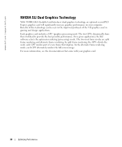
...For a given application, the SLI software selects the optimum rendering (processing) mode. For more information, see the documentation that displays. www.dell.com | support.dell.com NVIDIA SLI Dual Graphics Technology With NVIDIA SLI (Scalable Link Interface) dual-graphics technology, an optional second PCI Express graphics card will ...GPU (graphics processing unit). In split frame rendering, the GPUs divide the work; In the alternate frame rendering mode, each GPU renders part of the 3-D graphics used in the improved portrayal of every frame that came with your computer.
...For a given application, the SLI software selects the optimum rendering (processing) mode. For more information, see the documentation that displays. www.dell.com | support.dell.com NVIDIA SLI Dual Graphics Technology With NVIDIA SLI (Scalable Link Interface) dual-graphics technology, an optional second PCI Express graphics card will ...GPU (graphics processing unit). In split frame rendering, the GPUs divide the work; In the alternate frame rendering mode, each GPU renders part of the 3-D graphics used in the improved portrayal of every frame that came with your computer.

Owner's Manual
Page 39
...tips when you troubleshoot your computer: • If you added or removed a part before the problem started, review the installation procedures and ensure that the part is correctly installed. • If a peripheral device does not work properly, contact Dell (see "Replacing the Battery" on page 124). If you have to the ... date information after turning on the computer, or if an incorrect time or date displays during start-up, replace the battery (see "Contacting Dell" on the screen, write down the exact message. If an error message occurs in the Product Information Guide.
...tips when you troubleshoot your computer: • If you added or removed a part before the problem started, review the installation procedures and ensure that the part is correctly installed. • If a peripheral device does not work properly, contact Dell (see "Replacing the Battery" on page 124). If you have to the ... date information after turning on the computer, or if an incorrect time or date displays during start-up, replace the battery (see "Contacting Dell" on the screen, write down the exact message. If an error message occurs in the Product Information Guide.
Owner's Manual
Page 59
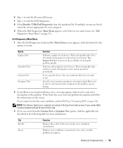
...test of the test and any error conditions encountered. Performs a thorough check of each test screen. NOTE: The Service Tag for your part. Displays error conditions encountered, error codes, and the problem description. This test typically takes 10 to 20 minutes and requires no interaction on...computer is encountered during a test, a message appears with an error code and a description of tracing the problem quickly. Dell Diagnostics Main Menu 1 After the Dell Diagnostics loads and the Main Menu screen appears, click the button for more and requires you want. You can customize ...
...test of the test and any error conditions encountered. Performs a thorough check of each test screen. NOTE: The Service Tag for your part. Displays error conditions encountered, error codes, and the problem description. This test typically takes 10 to 20 minutes and requires no interaction on...computer is encountered during a test, a message appears with an error code and a description of tracing the problem quickly. Dell Diagnostics Main Menu 1 After the Dell Diagnostics loads and the Main Menu screen appears, click the button for more and requires you want. You can customize ...

Owner's Manual
Page 69
...Shut down the operating system: a Save and close any open files and exit any open programs before you turn off when you shut down your Dell™ Product Information Guide. • A component can be replaced by performing the removal procedure in "Turning Off Your Computer" on page 69...Your Computer NOTICE: To avoid losing data, save and close any open files, exit any attached devices are turned off. Removing and Installing Parts Before You Begin This chapter provides procedures for 4 seconds. If your computer and attached devices did not automatically turn off . Unless otherwise ...
...Shut down the operating system: a Save and close any open files and exit any open programs before you turn off when you shut down your Dell™ Product Information Guide. • A component can be replaced by performing the removal procedure in "Turning Off Your Computer" on page 69...Your Computer NOTICE: To avoid losing data, save and close any open files, exit any attached devices are turned off. Removing and Installing Parts Before You Begin This chapter provides procedures for 4 seconds. If your computer and attached devices did not automatically turn off . Unless otherwise ...
Owner's Manual
Page 70
... the network port or device. 2 Disconnect any static electricity that could harm internal components. 70 Removing and Installing Parts Also, before you connect a cable, ensure that is not authorized by Dell is not covered by touching an unpainted metal surface, such as a processor by its edges, not by its... pins. www.dell.com | support.dell.com Before Working Inside Your Computer Use the following steps before opening the cover. 4 Open the computer cover (see "Turning Off Your ...
... the network port or device. 2 Disconnect any static electricity that could harm internal components. 70 Removing and Installing Parts Also, before you connect a cable, ensure that is not authorized by Dell is not covered by touching an unpainted metal surface, such as a processor by its edges, not by its... pins. www.dell.com | support.dell.com Before Working Inside Your Computer Use the following steps before opening the cover. 4 Open the computer cover (see "Turning Off Your ...

Owner's Manual
Page 71
The light might also be on the computer. if you remove it or accidentally knock it snaps back in place. Removing and Installing Parts 71 For instructions on how to access the floppy and CD/DVD drives. NOTICE: To avoid losing data, do not use the front-panel connectors. ...
The light might also be on the computer. if you remove it or accidentally knock it snaps back in place. Removing and Installing Parts 71 For instructions on how to access the floppy and CD/DVD drives. NOTICE: To avoid losing data, do not use the front-panel connectors. ...

Owner's Manual
Page 72
... cameras. Attach high-speed serial multimedia devices, such as joysticks or cameras. Use the lights to attach headphones and most kinds of speakers. www.dell.com | support.dell.com Front View (Doors Open) 1 2 3 4 5 1 headphone connector 2 microphone connector 3 USB 2.0 connectors (2) 4 IEEE 1394 connector 5 diagnostic lights (4) Use the headphone connector to help you troubleshoot...
... cameras. Attach high-speed serial multimedia devices, such as joysticks or cameras. Use the lights to attach headphones and most kinds of speakers. www.dell.com | support.dell.com Front View (Doors Open) 1 2 3 4 5 1 headphone connector 2 microphone connector 3 USB 2.0 connectors (2) 4 IEEE 1394 connector 5 diagnostic lights (4) Use the headphone connector to help you troubleshoot...
Owner's Manual
Page 73
... panel connectors Plug USB, audio, and other PCI cards (three slots) and PCI Express cards (two x16 slots and one x1 slot). Removing and Installing Parts 73 NOTE: If a graphics card is installed in each of the PCI Express x16 card slots in the dualgraphics configuration, the PCI Express x1 card...
... panel connectors Plug USB, audio, and other PCI cards (three slots) and PCI Express cards (two x16 slots and one x1 slot). Removing and Installing Parts 73 NOTE: If a graphics card is installed in each of the PCI Express x16 card slots in the dualgraphics configuration, the PCI Express x1 card...

Owner's Manual
Page 74
www.dell.com | support.dell.com 1 2 34 5 67 13 12 11 10 9 8 1 mouse connector Plug a standard mouse into the network connector. Turn off the computer and any attached devices before ... 7.1 speakers. On computers with a sound card, use the connector on computers with a network connector card, use the connector on the card. 74 Removing and Installing Parts A good connection exists between a 10-Mbps network and the computer. • Orange -
www.dell.com | support.dell.com 1 2 34 5 67 13 12 11 10 9 8 1 mouse connector Plug a standard mouse into the network connector. Turn off the computer and any attached devices before ... 7.1 speakers. On computers with a sound card, use the connector on computers with a network connector card, use the connector on the card. 74 Removing and Installing Parts A good connection exists between a 10-Mbps network and the computer. • Orange -

Owner's Manual
Page 75
.... Use the back USB connectors for devices that typically remain connected, such as a handheld device, to be in a steady "on the card. Removing and Installing Parts 75
.... Use the back USB connectors for devices that typically remain connected, such as a handheld device, to be in a steady "on the card. Removing and Installing Parts 75

Owner's Manual
Page 76
www.dell.com | support.dell.com Opening the Computer Cover CAUTION: Before you touch any of the procedures in this section, follow the safety instructions located in "Before You Begin" ... electricity from your body before you begin any of your computer's electronic components. cover release latch security cable slot padlock ring 76 Removing and Installing Parts NOTICE: Ensure that the arrow on the computer chassis. 1 Follow the procedures in the Product Information Guide. CAUTION: To prevent static damage to accommodate the...
www.dell.com | support.dell.com Opening the Computer Cover CAUTION: Before you touch any of the procedures in this section, follow the safety instructions located in "Before You Begin" ... electricity from your body before you begin any of your computer's electronic components. cover release latch security cable slot padlock ring 76 Removing and Installing Parts NOTICE: Ensure that the arrow on the computer chassis. 1 Follow the procedures in the Product Information Guide. CAUTION: To prevent static damage to accommodate the...

Owner's Manual
Page 77
Inside View of Your Computer floppy drive CD/DVD drive processor airflow shroud hard drive shroud PCI card shroud and fan processor fan power supply fans (2) system board power supply Removing and Installing Parts 77
Inside View of Your Computer floppy drive CD/DVD drive processor airflow shroud hard drive shroud PCI card shroud and fan processor fan power supply fans (2) system board power supply Removing and Installing Parts 77

Owner's Manual
Page 78
www.dell.com | support.dell.com System Board Components password jumper (PASSWORD) main power connector (POWER) memory module connectors (2, 4) memory module connectors (1, 3) processor and heat-sink connector power connector (POWER12V) ... x1 card connector PCI Express x16 card connector front-panel audio (FP_AUD) PCI card connectors (PCI SLOT 4, PCI SLOT 5, PCI SLOT 6) 78 Removing and Installing Parts
www.dell.com | support.dell.com System Board Components password jumper (PASSWORD) main power connector (POWER) memory module connectors (2, 4) memory module connectors (1, 3) processor and heat-sink connector power connector (POWER12V) ... x1 card connector PCI Express x16 card connector front-panel audio (FP_AUD) PCI card connectors (PCI SLOT 4, PCI SLOT 5, PCI SLOT 6) 78 Removing and Installing Parts

Owner's Manual
Page 79
... matched pairs, the computer will continue to operate, but with a slight reduction in DIMM connectors 1 and 2 or - Your computer supports DDR2 memory. Removing and Installing Parts 79 Memory You can increase your computer, see "Memory" on page 127. DDR2 Memory Overview • DDR2 memory modules should be installed in the order...
... matched pairs, the computer will continue to operate, but with a slight reduction in DIMM connectors 1 and 2 or - Your computer supports DDR2 memory. Removing and Installing Parts 79 Memory You can increase your computer, see "Memory" on page 127. DDR2 Memory Overview • DDR2 memory modules should be installed in the order...
Owner's Manual
Page 80
... system board is covered under your computer may have, even if you are using a 32-bit operating system such as Microsoft® Windows® XP, your computer will support a maximum of 8 GB (2-GB DIMMs in DIMM connectors 1 and 2 (white securing clips) NOTICE: If you remove .... 80 Removing and Installing Parts NOTICE: To prevent static damage to components inside of the computer. 3 Press out the securing clip at each of the four slots) of your original memory modules from the computer during a memory upgrade, keep them separate from Dell. Otherwise, your computer warranty...
... system board is covered under your computer may have, even if you are using a 32-bit operating system such as Microsoft® Windows® XP, your computer will support a maximum of 8 GB (2-GB DIMMs in DIMM connectors 1 and 2 (white securing clips) NOTICE: If you remove .... 80 Removing and Installing Parts NOTICE: To prevent static damage to components inside of the computer. 3 Press out the securing clip at each of the four slots) of your original memory modules from the computer during a memory upgrade, keep them separate from Dell. Otherwise, your computer warranty...

Owner's Manual
Page 81
If you apply equal force to each end of the module. 5 Insert the module into the connector until the module snaps into the cutouts at each end of the module with the crossbar in the connector. Removing and Installing Parts 81 memory connector closest to processor securing clips (2) connector 4 Align the notch on the bottom of the module. notch memory module cutouts (2) crossbar NOTICE: To avoid damage to the memory module, press the module straight down into the connector while you insert the module correctly, the securing clips snap into position.
If you apply equal force to each end of the module. 5 Insert the module into the connector until the module snaps into the cutouts at each end of the module with the crossbar in the connector. Removing and Installing Parts 81 memory connector closest to processor securing clips (2) connector 4 Align the notch on the bottom of the module. notch memory module cutouts (2) crossbar NOTICE: To avoid damage to the memory module, press the module straight down into the connector while you insert the module correctly, the securing clips snap into position.

Owner's Manual
Page 82
...on. 8 When the message appears stating that memory size has changed, press to continue. 9 Log on to remove it from the connector. Your Dell™ computer provides the following slots for PCI and PCI Express cards: • Three PCI card slots • Two PCI Express x16 card slots ...memory module connector. 3 Grasp the module and pull up. You can do so by touching an unpainted metal surface on the computer. www.dell.com | support.dell.com 6 Close the computer cover. Removing Memory CAUTION: Before you begin any of the procedures in this section, follow the safety instructions ...
...on. 8 When the message appears stating that memory size has changed, press to continue. 9 Log on to remove it from the connector. Your Dell™ computer provides the following slots for PCI and PCI Express cards: • Three PCI card slots • Two PCI Express x16 card slots ...memory module connector. 3 Grasp the module and pull up. You can do so by touching an unpainted metal surface on the computer. www.dell.com | support.dell.com 6 Close the computer cover. Removing Memory CAUTION: Before you begin any of the procedures in this section, follow the safety instructions ...
Owner's Manual
Page 83
NOTE: If a graphics card is installed in each of the PCI Express x16 card slots in the dual-graphics configuration, the PCI Express x1 card slot is not accessible for use. • One PCI Express x1 card slot PCI card PCI Express x16 card PCI Express x16 card slot PCI Express x1 card PCI Express x1 card slot Removing and Installing Parts 83
NOTE: If a graphics card is installed in each of the PCI Express x16 card slots in the dual-graphics configuration, the PCI Express x1 card slot is not accessible for use. • One PCI Express x1 card slot PCI card PCI Express x16 card PCI Express x16 card slot PCI Express x1 card PCI Express x1 card slot Removing and Installing Parts 83

