
Setup and Features Information Tech Sheet
Page 4
.... The following specifications are only those required by law to a docking device or other external device, such as a printer. System Information Chipset Intel® GM45 Processor Processor • Intel Core™2 Duo • Intel Celeron®(Socket P) Video Video type integrated on the computer. NOTE: It is recommended that you turn on...
.... The following specifications are only those required by law to a docking device or other external device, such as a printer. System Information Chipset Intel® GM45 Processor Processor • Intel Core™2 Duo • Intel Celeron®(Socket P) Video Video type integrated on the computer. NOTE: It is recommended that you turn on...
Service Manual
Page 14
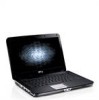
... the WLAN card. 6. Follow the procedures in Before Working Inside Your Computer. 2. Remove the control panel cover. 7. Remove the display assembly. 9. Back to Contents Page Processor Fan Dell™ Vostro™ 1014/1015 Service Manual WARNING: Before working inside your computer, read the safety information that shipped with your computer. Removing the...
... the WLAN card. 6. Follow the procedures in Before Working Inside Your Computer. 2. Remove the control panel cover. 7. Remove the display assembly. 9. Back to Contents Page Processor Fan Dell™ Vostro™ 1014/1015 Service Manual WARNING: Before working inside your computer, read the safety information that shipped with your computer. Removing the...

Service Manual
Page 15
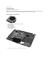
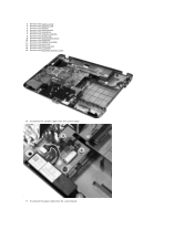
11. Remove the screw that secures the processor fan to the computer. 12. Lift the processor fan from the computer.
11. Remove the screw that secures the processor fan to the computer. 12. Lift the processor fan from the computer.

Service Manual
Page 16
Replacing the Processor Fan Perform the above steps in the reverse order to Contents Page Back to replace the processor fan.
Replacing the Processor Fan Perform the above steps in the reverse order to Contents Page Back to replace the processor fan.
Service Manual
Page 23
...screws that shipped with your computer, read the safety information that secure the heat sink to Contents Page Heat Sink Dell™ Vostro™ 1014/1015 Service Manual WARNING: Before working inside your computer. Remove the control panel cover. 10. Remove the palm rest...15. Remove the keyboard. 11. Remove the WLAN card. 9. Remove the Bluetooth wireless card. 16. Remove the ExpressCard (if applicable). 3. Remove the processor fan. 14. Remove the battery. 5. Remove the memory modules. 8. Remove the display assembly. 12. Remove the access panel. 6. For additional safety ...
...screws that shipped with your computer, read the safety information that secure the heat sink to Contents Page Heat Sink Dell™ Vostro™ 1014/1015 Service Manual WARNING: Before working inside your computer. Remove the control panel cover. 10. Remove the palm rest...15. Remove the keyboard. 11. Remove the WLAN card. 9. Remove the Bluetooth wireless card. 16. Remove the ExpressCard (if applicable). 3. Remove the processor fan. 14. Remove the battery. 5. Remove the memory modules. 8. Remove the display assembly. 12. Remove the access panel. 6. For additional safety ...
Service Manual
Page 40
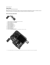
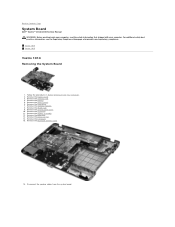
...4. Remove the access panel. 6. Remove the palm rest. 13. Vostro 1014 Vostro 1015 Vostro 1014 Removing the System Board 1. Remove the battery. 5. Remove the keyboard. 11. Remove the I/O board. 15. Back to Contents Page System Board Dell™ Vostro™ 1014/1015 Service Manual WARNING: Before working inside your computer, read the safety.... 16. Remove the memory modules. 8. Disconnect the speaker cables from the system board. Remove the WLAN card. 9. Remove the processor fan. 14. For additional safety best practices information, see the Regulatory Compliance Homepage at www...
...4. Remove the access panel. 6. Remove the palm rest. 13. Vostro 1014 Vostro 1015 Vostro 1014 Removing the System Board 1. Remove the battery. 5. Remove the keyboard. 11. Remove the I/O board. 15. Back to Contents Page System Board Dell™ Vostro™ 1014/1015 Service Manual WARNING: Before working inside your computer, read the safety.... 16. Remove the memory modules. 8. Disconnect the speaker cables from the system board. Remove the WLAN card. 9. Remove the processor fan. 14. For additional safety best practices information, see the Regulatory Compliance Homepage at www...
Service Manual
Page 43
2. Remove the hard drive. 7. Remove the keyboard. 11. Remove the processor fan. 14. Remove the I/O board. 15. Remove the Bluetooth wireless card. 16. Remove the ExpressCard. 3. Remove the memory card. 4. Remove the control panel cover. 10. Disconnect the speaker cables from the system board. Remove the access panel. 6. Remove the WLAN card. 9. Remove the palm rest. 13. Remove the battery. 5. Disconnect the power cable from the system board. 17. Remove the display assembly. 12. Remove the memory modules. 8.
2. Remove the hard drive. 7. Remove the keyboard. 11. Remove the processor fan. 14. Remove the I/O board. 15. Remove the Bluetooth wireless card. 16. Remove the ExpressCard. 3. Remove the memory card. 4. Remove the control panel cover. 10. Disconnect the speaker cables from the system board. Remove the access panel. 6. Remove the WLAN card. 9. Remove the palm rest. 13. Remove the battery. 5. Disconnect the power cable from the system board. 17. Remove the display assembly. 12. Remove the memory modules. 8.
Service Manual
Page 58
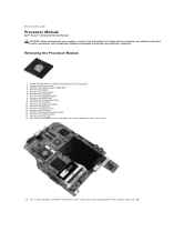
.... Remove the WLAN card. 9. Use a small, flat-blade screwdriver and rotate the ZIF-socket cam screw counterclockwise until it comes to Contents Page Processor Module Dell™ Vostro™ 1014/1015 Service Manual WARNING: Before working inside your computer, read the safety information that shipped with your computer. Remove the control panel cover. 10...
.... Remove the WLAN card. 9. Use a small, flat-blade screwdriver and rotate the ZIF-socket cam screw counterclockwise until it comes to Contents Page Processor Module Dell™ Vostro™ 1014/1015 Service Manual WARNING: Before working inside your computer, read the safety information that shipped with your computer. Remove the control panel cover. 10...

Service Manual
Page 59
Replacing the Processor Module Perform the above steps in the reverse order to Contents Page Back to replace the processor module. 20. Remove the heat sink from the system board.
Replacing the Processor Module Perform the above steps in the reverse order to Contents Page Back to replace the processor module. 20. Remove the heat sink from the system board.
Service Manual
Page 60
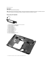
...Remove the memory modules. 8. Remove the WLAN card. 9. Remove the Bluetooth® wireless card. 16. Back to Contents Page Speaker Dell™ Vostro™ 1014/1015 Service Manual WARNING: Before working inside your computer. Remove the system board. 17. Remove the ExpressCard (if applicable). 3. Remove the...control panel cover. 10. Remove the display assembly. 12. Follow the procedures in Before Working Inside Your Computer. 2. Remove the processor fan. 14. Remove the I/O board. 15. Remove the palm rest. 13. For additional safety best practices information, see the ...
...Remove the memory modules. 8. Remove the WLAN card. 9. Remove the Bluetooth® wireless card. 16. Back to Contents Page Speaker Dell™ Vostro™ 1014/1015 Service Manual WARNING: Before working inside your computer. Remove the system board. 17. Remove the ExpressCard (if applicable). 3. Remove the...control panel cover. 10. Remove the display assembly. 12. Follow the procedures in Before Working Inside Your Computer. 2. Remove the processor fan. 14. Remove the I/O board. 15. Remove the palm rest. 13. For additional safety best practices information, see the ...

Service Manual
Page 65
...; Memory Installed ¡ Memory Available ¡ Memory Speed ¡ Memory Channel Mode ¡ Memory Technology ¡ DIMM A Size ¡ DIMM B Size l Processor Information ¡ Processor Type ¡ Core Count ¡ Processor ID ¡ Current Clock Speed ¡ Minimum Clock Speed ¡ Maximum Clock Speed l Device Information ¡ Primary Hard Drive ¡ Fixed Bay...
...; Memory Installed ¡ Memory Available ¡ Memory Speed ¡ Memory Channel Mode ¡ Memory Technology ¡ DIMM A Size ¡ DIMM B Size l Processor Information ¡ Processor Type ¡ Core Count ¡ Processor ID ¡ Current Clock Speed ¡ Minimum Clock Speed ¡ Maximum Clock Speed l Device Information ¡ Primary Hard Drive ¡ Fixed Bay...
Service Manual
Page 68
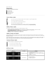
Back to Contents Page Diagnostics Dell™ Vostro™ 1014/1015 Service Manual Device Status Lights Battery Status Lights ... outlet, the battery light operates as follows: l Alternately blinking amber light and blue light - Replace the processor. Turns on when the Caps Lock function is enabled. Battery Status Lights If the computer is attached to .... For example, if four lights are installed Next Step 1. FLASH-ON-ON System board error 1. Reseat the processor. 2. Battery Charge and Health To check the battery charge, press and release the status button on when the ...
Back to Contents Page Diagnostics Dell™ Vostro™ 1014/1015 Service Manual Device Status Lights Battery Status Lights ... outlet, the battery light operates as follows: l Alternately blinking amber light and blue light - Replace the processor. Turns on when the Caps Lock function is enabled. Battery Status Lights If the computer is attached to .... For example, if four lights are installed Next Step 1. FLASH-ON-ON System board error 1. Reseat the processor. 2. Battery Charge and Health To check the battery charge, press and release the status button on when the ...
Service Manual
Page 70
Back to Contents Page Adding and Replacing Parts Dell™ Vostro™ 1014/1015 Service Manual ExpressCard Battery Access Panel Memory Control Panel Cover Display Assembly Processor Fan I/O Board System Board Heat Sink Back to Contents Page Memory Card Optical Drive Hard Drive WLAN Card Keyboard Palm Rest Coin-Cell Battery Internal Card with Bluetooth® Wireless Technology Speaker Processor
Back to Contents Page Adding and Replacing Parts Dell™ Vostro™ 1014/1015 Service Manual ExpressCard Battery Access Panel Memory Control Panel Cover Display Assembly Processor Fan I/O Board System Board Heat Sink Back to Contents Page Memory Card Optical Drive Hard Drive WLAN Card Keyboard Palm Rest Coin-Cell Battery Internal Card with Bluetooth® Wireless Technology Speaker Processor
Service Manual
Page 71
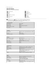
... EPROM Intel® GM45 64 bits dual-channel (2) 64 bit buses 36 bits 1 MB Processor Processor type L2 cache External bus frequency Intel Core 2 Duo, or Intel Celeron® processors (Socket P) 3 MB or 6 MB 667 and 800 MHz Memory Memory module connectors Memory...in -1 Memory Card Reader Display Camera (Optional) Physical Processor Communications Keyboard Ports and Connectors Video Touch Pad AC Adapter Environmental NOTE: Offerings may vary by region. Back to Contents Page Specifications Dell™ Vostro™ 1014/1015 Service Manual System Information Memory Audio Battery 5-in ...
... EPROM Intel® GM45 64 bits dual-channel (2) 64 bit buses 36 bits 1 MB Processor Processor type L2 cache External bus frequency Intel Core 2 Duo, or Intel Celeron® processors (Socket P) 3 MB or 6 MB 667 and 800 MHz Memory Memory module connectors Memory...in -1 Memory Card Reader Display Camera (Optional) Physical Processor Communications Keyboard Ports and Connectors Video Touch Pad AC Adapter Environmental NOTE: Offerings may vary by region. Back to Contents Page Specifications Dell™ Vostro™ 1014/1015 Service Manual System Information Memory Audio Battery 5-in ...
Service Manual
Page 75
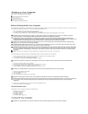
... perform the following conditions exist: l You have performed the steps in your computer. Turn off your product documentation, or as a processor by its metal mounting bracket. Remove any adapters from your personal safety. l You have connectors with care. For additional safety best practices...Damage due to servicing that came with your computer, ground yourself by its pull-tab, not on Your Computer Dell™ Vostro™ 1014/1015 Service Manual Before Working Inside Your Computer Recommended Tools Turning Off Your Computer After Working Inside Your Computer Before ...
... perform the following conditions exist: l You have performed the steps in your computer. Turn off your product documentation, or as a processor by its metal mounting bracket. Remove any adapters from your personal safety. l You have connectors with care. For additional safety best practices...Damage due to servicing that came with your computer, ground yourself by its pull-tab, not on Your Computer Dell™ Vostro™ 1014/1015 Service Manual Before Working Inside Your Computer Recommended Tools Turning Off Your Computer After Working Inside Your Computer Before ...


