
Service Manual
Page 29
Back to replace the keyboard. Replacing the Keyboard Perform the above steps in the reverse order to Contents Page
Back to replace the keyboard. Replacing the Keyboard Perform the above steps in the reverse order to Contents Page
Service Manual
Page 30
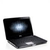
... Display Assembly Removing the Display Bezel Replacing the Display Bezel Removing the LED Display Panel Replacing the LED Display Panel Removing the Display Camera Replacing the Display Camera Removing the Display Inverter Cable Replacing the Display Inverter Cable Removing the Display .... 2. Remove the keyboard. 8. Remove the battery. 3. For additional safety best practices information, see the Regulatory Compliance Homepage at www.dell.com/regulatory_compliance. Remove the access panel. 4. Back to Contents Page Display Dell™ Vostro™ 1014/1015 Service Manual WARNING...
... Display Assembly Removing the Display Bezel Replacing the Display Bezel Removing the LED Display Panel Replacing the LED Display Panel Removing the Display Camera Replacing the Display Camera Removing the Display Inverter Cable Replacing the Display Inverter Cable Removing the Display .... 2. Remove the keyboard. 8. Remove the battery. 3. For additional safety best practices information, see the Regulatory Compliance Homepage at www.dell.com/regulatory_compliance. Remove the access panel. 4. Back to Contents Page Display Dell™ Vostro™ 1014/1015 Service Manual WARNING...
Service Manual
Page 33
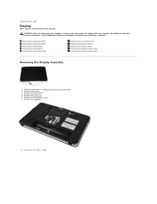
Remove the access panel. 4. Remove the WLAN card. 6. Remove the keyboard. 8. Remove the display assembly. Removing the Display Bezel 1. Remove the control panel cover. 7. Remove the hard drive. 5. Follow the procedures in the reverse order to replace the display assembly. Remove the battery. 3. Replacing the Display Assembly Perform the above steps in Before Working Inside Your Computer. 2.
Remove the access panel. 4. Remove the WLAN card. 6. Remove the keyboard. 8. Remove the display assembly. Removing the Display Bezel 1. Remove the control panel cover. 7. Remove the hard drive. 5. Follow the procedures in the reverse order to replace the display assembly. Remove the battery. 3. Replacing the Display Assembly Perform the above steps in Before Working Inside Your Computer. 2.

Service Manual
Page 35
Replacing the Display Bezel Perform the above steps in Before Working Inside Your Computer. 2. Remove the battery. 3. Remove the WLAN card. 6. 11. Removing the Display LED Panel 1. Remove the hard drive. 5. Follow the procedures in the reverse order to replace the display bezel into the display assembly. Remove the control panel cover. 7. Remove the display bezel. Remove the keyboard. Remove the access panel. 4.
Replacing the Display Bezel Perform the above steps in Before Working Inside Your Computer. 2. Remove the battery. 3. Remove the WLAN card. 6. 11. Removing the Display LED Panel 1. Remove the hard drive. 5. Follow the procedures in the reverse order to replace the display bezel into the display assembly. Remove the control panel cover. 7. Remove the display bezel. Remove the keyboard. Remove the access panel. 4.

Service Manual
Page 37
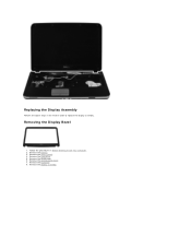
Remove the control panel cover. 7. Remove the display bezel. 10. Remove the hard drive. 5. Remove the display assembly. 9. Follow the procedures in the reverse to replace the display LED panel. Remove the access panel. 4. Remove the WLAN card. 6. Replacing the Display LED Panel Perform the above steps in Before Working Inside Your Computer. 2. Removing the Display Camera 1. Remove the battery. 3. Remove the keyboard. 8. Lift the display LED panel from the display assembly. Remove the display LED panel. 12.
Remove the control panel cover. 7. Remove the display bezel. 10. Remove the hard drive. 5. Remove the display assembly. 9. Follow the procedures in the reverse to replace the display LED panel. Remove the access panel. 4. Remove the WLAN card. 6. Replacing the Display LED Panel Perform the above steps in Before Working Inside Your Computer. 2. Removing the Display Camera 1. Remove the battery. 3. Remove the keyboard. 8. Lift the display LED panel from the display assembly. Remove the display LED panel. 12.

Service Manual
Page 38
Removing the Display Inverter Cable 1. Remove the keyboard. 8. Remove the display bezel. 10. Replacing the Display Camera Perform the above steps in Before Working Inside Your Computer. 2. Remove the access panel. 4. Remove the control panel cover. 7. Remove the ... the battery. 3. Remove the hard drive. 5. Lift the display camera from there to the display camera. Follow the procedures in the reverse order to replace the display camera into its bracket, and from the display assembly. 13. Remove the display LED panel. 11. Remove the two screws that secure the...
Removing the Display Inverter Cable 1. Remove the keyboard. 8. Remove the display bezel. 10. Replacing the Display Camera Perform the above steps in Before Working Inside Your Computer. 2. Remove the access panel. 4. Remove the control panel cover. 7. Remove the ... the battery. 3. Remove the hard drive. 5. Lift the display camera from there to the display camera. Follow the procedures in the reverse order to replace the display camera into its bracket, and from the display assembly. 13. Remove the display LED panel. 11. Remove the two screws that secure the...
Service Manual
Page 68
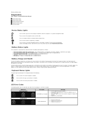
Back to Contents Page Diagnostics Dell™ Vostro™ 1014/1015 Service Manual Device Status Lights Battery Status Lights Battery Charge and Health Keyboard Status Lights LED Error Codes Device Status Lights Turns on when you should consider replacing the battery. To turn on when wireless networking is enabled. Battery Status Lights If the computer is...
Back to Contents Page Diagnostics Dell™ Vostro™ 1014/1015 Service Manual Device Status Lights Battery Status Lights Battery Charge and Health Keyboard Status Lights LED Error Codes Device Status Lights Turns on when you should consider replacing the battery. To turn on when wireless networking is enabled. Battery Status Lights If the computer is...
Service Manual
Page 70
Back to Contents Page Adding and Replacing Parts Dell™ Vostro™ 1014/1015 Service Manual ExpressCard Battery Access Panel Memory Control Panel Cover Display Assembly Processor Fan I/O Board System Board Heat Sink Back to Contents Page Memory Card Optical Drive Hard Drive WLAN Card Keyboard Palm Rest Coin-Cell Battery Internal Card with Bluetooth® Wireless Technology Speaker Processor
Back to Contents Page Adding and Replacing Parts Dell™ Vostro™ 1014/1015 Service Manual ExpressCard Battery Access Panel Memory Control Panel Cover Display Assembly Processor Fan I/O Board System Board Heat Sink Back to Contents Page Memory Card Optical Drive Hard Drive WLAN Card Keyboard Palm Rest Coin-Cell Battery Internal Card with Bluetooth® Wireless Technology Speaker Processor


