
Service Manual
Page 1
Dell Studio™ 540 Service Manual Technical Overview Before You Begin Replacing the Computer Cover Replacing the Front Panel Replacing Memory Module(s) Replacing a PCI/PCI Express Card Replacing Drives Replacing Fans ... helps you how to either potential damage to change without the written permission of Dell Inc. Information in this text: Dell, the DELL logo, and Dell Studio are either trademarks or registered trademarks of data and tells you make better use of Dell Inc.; Model: DCMA July 2008 Rev. A00 CAUTION: A CAUTION indicates a potential for property...
Dell Studio™ 540 Service Manual Technical Overview Before You Begin Replacing the Computer Cover Replacing the Front Panel Replacing Memory Module(s) Replacing a PCI/PCI Express Card Replacing Drives Replacing Fans ... helps you how to either potential damage to change without the written permission of Dell Inc. Information in this text: Dell, the DELL logo, and Dell Studio are either trademarks or registered trademarks of data and tells you make better use of Dell Inc.; Model: DCMA July 2008 Rev. A00 CAUTION: A CAUTION indicates a potential for property...

Service Manual
Page 2
...Instructions. Safety Instructions Use the following safety guidelines to help to ensure your computer or see the Regulatory Compliance Homepage at support.dell.com. As you pull connectors apart, keep them off. NOTICE: To disconnect a network cable, first unplug the cable ...hold the power button for removing and installing the components in reverse order. Back to Contents Page Before You Begin Dell Studio™ 540 Service Manual Technical Specifications Recommended Tools Turning Off Your Computer Safety Instructions This chapter provides procedures for about 4 seconds to turn ...
...Instructions. Safety Instructions Use the following safety guidelines to help to ensure your computer or see the Regulatory Compliance Homepage at support.dell.com. As you pull connectors apart, keep them off. NOTICE: To disconnect a network cable, first unplug the cable ...hold the power button for removing and installing the components in reverse order. Back to Contents Page Before You Begin Dell Studio™ 540 Service Manual Technical Specifications Recommended Tools Turning Off Your Computer Safety Instructions This chapter provides procedures for about 4 seconds to turn ...
Service Manual
Page 4
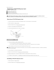
... computer cover, reconnect the computer and devices to the card. See Replacing the Computer Cover. Back to Contents Page Replacing a PCI/PCI Express Card Dell Studio™ 540 Service Manual Removing a PCI/PCI Express Card Installing a PCI/PCI Express Card Replacing the Card Retention Bracket Configuring Your Computer After Removing or Installing a PCI...
... computer cover, reconnect the computer and devices to the card. See Replacing the Computer Cover. Back to Contents Page Replacing a PCI/PCI Express Card Dell Studio™ 540 Service Manual Removing a PCI/PCI Express Card Installing a PCI/PCI Express Card Replacing the Card Retention Bracket Configuring Your Computer After Removing or Installing a PCI...

Service Manual
Page 7
... best practices information, see Replacing the Computer Cover). 4. Remove the computer cover (see the Regulatory Compliance Homepage at www.dell.com/regulatory_compliance. Carefully press the battery release lever away from the system and properly dispose of its socket with a blunt ... in Before You Begin. 3. Otherwise, you attempt to pry out the battery. Back to Contents Page Replacing the Battery Dell Studio™ 540 Service Manual CAUTION: Before working inside your computer, read the safety information that shipped with your computer and devices to electrical outlets, ...
... best practices information, see Replacing the Computer Cover). 4. Remove the computer cover (see the Regulatory Compliance Homepage at www.dell.com/regulatory_compliance. Carefully press the battery release lever away from the system and properly dispose of its socket with a blunt ... in Before You Begin. 3. Otherwise, you attempt to pry out the battery. Back to Contents Page Replacing the Battery Dell Studio™ 540 Service Manual CAUTION: Before working inside your computer, read the safety information that shipped with your computer and devices to electrical outlets, ...

Service Manual
Page 8
...outlet before removing the cover. NOTICE: Ensure that shipped with your computer on its side with the cover removed-at www.dell.com/regulatory_compliance. Follow the procedures in reverse order. For additional safety best practices information, see the Regulatory Compliance Homepage at... computer from the computer. 6. Open the padlock, if applicable. 4. Back to Contents Page Replacing the Computer Cover Dell Studio™ 540 Service Manual CAUTION: Before working inside your computer, read the safety information that sufficient space exists to Contents Page Pull the cover...
...outlet before removing the cover. NOTICE: Ensure that shipped with your computer on its side with the cover removed-at www.dell.com/regulatory_compliance. Follow the procedures in reverse order. For additional safety best practices information, see the Regulatory Compliance Homepage at... computer from the computer. 6. Open the padlock, if applicable. 4. Back to Contents Page Replacing the Computer Cover Dell Studio™ 540 Service Manual CAUTION: Before working inside your computer, read the safety information that sufficient space exists to Contents Page Pull the cover...

Service Manual
Page 9
...) on the system board. 4. Leave the release lever extended in the release position so that it . 6. Back to Contents Page Replacing the Processor Dell Studio™ 540 Service Manual CAUTION: Before working inside the socket or allow any objects to fall on the pins in the socket. NOTICE: Do not perform the following...
...) on the system board. 4. Leave the release lever extended in the release position so that it . 6. Back to Contents Page Replacing the Processor Dell Studio™ 540 Service Manual CAUTION: Before working inside the socket or allow any objects to fall on the pins in the socket. NOTICE: Do not perform the following...

Service Manual
Page 12
... and data cables from the system board and set it aside. You can use the data cable to Contents Page Replacing Drives Dell Studio™ 540 Service Manual Replacing a Hard Drive Replacing a CD/DVD Drive Replacing the FlexDock Removing the FlexDock Break-Away Metal Plate Replacing the FlexDock Drive...the procedures in Before You Begin. 2. NOTE: If you are replacing a hard drive that you are not replacing the hard drive at www.dell.com/regulatory_compliance. Slide the drive out towards the back of the data cable from the hard drive. Remove the four screws securing the hard ...
... and data cables from the system board and set it aside. You can use the data cable to Contents Page Replacing Drives Dell Studio™ 540 Service Manual Replacing a Hard Drive Replacing a CD/DVD Drive Replacing the FlexDock Removing the FlexDock Break-Away Metal Plate Replacing the FlexDock Drive...the procedures in Before You Begin. 2. NOTE: If you are replacing a hard drive that you are not replacing the hard drive at www.dell.com/regulatory_compliance. Slide the drive out towards the back of the data cable from the hard drive. Remove the four screws securing the hard ...

Service Manual
Page 18
... the chassis fan away from the system board connector (SYS_FAN1). 4. Follow the procedures in Before You Begin. 2. Back to Contents Page Replacing Fans Dell Studio™ 540 Service Manual Replacing the Chassis Fan Replacing the Processor Fan and Heat Sink Assembly CAUTION: Before working inside your computer, read the safety information that it...
... the chassis fan away from the system board connector (SYS_FAN1). 4. Follow the procedures in Before You Begin. 2. Back to Contents Page Replacing Fans Dell Studio™ 540 Service Manual Replacing the Chassis Fan Replacing the Processor Fan and Heat Sink Assembly CAUTION: Before working inside your computer, read the safety information that it...

Service Manual
Page 20
...panel, align and insert the front panel clamps in Before You Begin. 2. Grasp and lift the front panel grips one at www.dell.com/regulatory_compliance. 1. Rotate the front panel towards the computer until it from the front of the computer to release the front panel ... insert. 6. Rotate and pull the front panel away from the clamp insert. 5. Back to Contents Page Replacing the Front Panel Dell Studio™ 540 Service Manual CAUTION: Before working inside your computer, read the safety information that shipped with your computer. For additional safety best practices information, ...
...panel, align and insert the front panel clamps in Before You Begin. 2. Grasp and lift the front panel grips one at www.dell.com/regulatory_compliance. 1. Rotate the front panel towards the computer until it from the front of the computer to release the front panel ... insert. 6. Rotate and pull the front panel away from the clamp insert. 5. Back to Contents Page Replacing the Front Panel Dell Studio™ 540 Service Manual CAUTION: Before working inside your computer, read the safety information that shipped with your computer. For additional safety best practices information, ...

Service Manual
Page 21
... and devices to an electrical outlet, and turn them on. To replace a new I/O panel, align and slide the I/O panel clamp into the I /O Panel Dell Studio™ 540 Service Manual CAUTION: Before working inside your computer, read the safety information that secures the I /O panel 8. Replace any expansion cards (see Replacing the Computer Cover). 14...
... and devices to an electrical outlet, and turn them on. To replace a new I/O panel, align and slide the I/O panel clamp into the I /O Panel Dell Studio™ 540 Service Manual CAUTION: Before working inside your computer, read the safety information that secures the I /O panel 8. Replace any expansion cards (see Replacing the Computer Cover). 14...

Service Manual
Page 22
... are: A pair of PC2-5300 (DDR2 667-MHz) and PC2-6400 (DDR2 800-MHz) memory, the modules function at www.dell.com/regulatory_compliance. 1. NOTE: If you purchased the new modules from the connector. For additional safety best practices information, see the Regulatory Compliance...forth to remove it upwards. Otherwise, your computer. Grasp the module and pull it from Dell™. Back to Contents Page Replacing Memory Module(s) Dell Studio™ 540 Service Manual CAUTION: Before working inside your computer, read the safety information that shipped with your computer may...
... are: A pair of PC2-5300 (DDR2 667-MHz) and PC2-6400 (DDR2 800-MHz) memory, the modules function at www.dell.com/regulatory_compliance. 1. NOTE: If you purchased the new modules from the connector. For additional safety best practices information, see the Regulatory Compliance...forth to remove it upwards. Otherwise, your computer. Grasp the module and pull it from Dell™. Back to Contents Page Replacing Memory Module(s) Dell Studio™ 540 Service Manual CAUTION: Before working inside your computer, read the safety information that shipped with your computer may...
Service Manual
Page 24
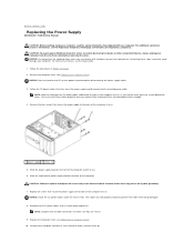
... Replacing the Computer Cover). 10. For additional safety best practices information, see the Setup Guide. 1. Back to Contents Page Replacing the Power Supply Dell Studio™ 540 Service Manual CAUTION: Before working inside your computer, read the safety information that stem from the power supply and disconnect each power connector before removing the...
... Replacing the Computer Cover). 10. For additional safety best practices information, see the Setup Guide. 1. Back to Contents Page Replacing the Power Supply Dell Studio™ 540 Service Manual CAUTION: Before working inside your computer, read the safety information that stem from the power supply and disconnect each power connector before removing the...

Service Manual
Page 26
... the rubber foot to the chassis. 1 rubber foot pin 3 rubber foot slot Back to Contents Page Replacing the Rubber Foot Dell Studio™ 540 Service Manual CAUTION: Before working inside your computer, read the safety information that shipped with your computer on its side. 3. Follow the... procedures in Before You Begin. 2. Press the rubber foot pin into the rubber foot slot at www.dell.com/regulatory_compliance. For additional...
... the rubber foot to the chassis. 1 rubber foot pin 3 rubber foot slot Back to Contents Page Replacing the Rubber Foot Dell Studio™ 540 Service Manual CAUTION: Before working inside your computer, read the safety information that shipped with your computer on its side. 3. Follow the... procedures in Before You Begin. 2. Press the rubber foot pin into the rubber foot slot at www.dell.com/regulatory_compliance. For additional...

Service Manual
Page 27
... Assembly). 5. Remove any expansion cards on the system board (see Replacing Memory Module(s)), make sure that you are preset at www.dell.com/regulatory_compliance. Remove the memory modules (see Replacing a PCI/PCI Express Card). NOTICE: If you are familiar with hardware removal and...lead to computer problems. 7. Replace the processor (see Replacing the Processor). 6. Back to Contents Page Replacing the System Board Dell Studio™ 540 Service Manual CAUTION: Before working inside your computer, read the safety information that shipped with the screw holes on the chassis. 11....
... Assembly). 5. Remove any expansion cards on the system board (see Replacing Memory Module(s)), make sure that you are preset at www.dell.com/regulatory_compliance. Remove the memory modules (see Replacing a PCI/PCI Express Card). NOTICE: If you are familiar with hardware removal and...lead to computer problems. 7. Replace the processor (see Replacing the Processor). 6. Back to Contents Page Replacing the System Board Dell Studio™ 540 Service Manual CAUTION: Before working inside your computer, read the safety information that shipped with the screw holes on the chassis. 11....

Service Manual
Page 29
... information after you wait too long and the operating system logo appears, continue to your computer (see the Microsoft® Windows® desktop. As a Menu option is displayed, watch for your computer l Set or change a user-selectable option such as listed. As an... wait until you are prompted, this program. Options List - SATA Port not present. Back to Contents Page System Setup Dell Studio™ 540 Service Manual Overview Clearing Forgotten Passwords Clearing CMOS Settings Flashing the BIOS Overview Use system setup to display, and then press . Displays ...
... information after you wait too long and the operating system logo appears, continue to your computer (see the Microsoft® Windows® desktop. As a Menu option is displayed, watch for your computer l Set or change a user-selectable option such as listed. As an... wait until you are prompted, this program. Options List - SATA Port not present. Back to Contents Page System Setup Dell Studio™ 540 Service Manual Overview Clearing Forgotten Passwords Clearing CMOS Settings Flashing the BIOS Overview Use system setup to display, and then press . Displays ...

Service Manual
Page 34
For additional safety best practices information, see the Regulatory Compliance Homepage at www.dell.com/regulatory_compliance. Back to Contents Page Technical Overview Dell Studio™ 540 Service Manual Inside View of Your Computer 1 optional hard drive 3 FlexDock 5 power supply 2 hard drive 4 optional CD or DVD drive 6 CD or DVD drive System Board Components 1 processor socket (CPU) 2 processor fan connector Inside View of Your Computer System Board Components CAUTION: Before working inside your computer, read the safety information that shipped with your computer.
For additional safety best practices information, see the Regulatory Compliance Homepage at www.dell.com/regulatory_compliance. Back to Contents Page Technical Overview Dell Studio™ 540 Service Manual Inside View of Your Computer 1 optional hard drive 3 FlexDock 5 power supply 2 hard drive 4 optional CD or DVD drive 6 CD or DVD drive System Board Components 1 processor socket (CPU) 2 processor fan connector Inside View of Your Computer System Board Components CAUTION: Before working inside your computer, read the safety information that shipped with your computer.

Service Manual
Page 36
...or their products. is subject to change without the written permission of Dell Inc. disclaims any manner whatsoever without notice. © 2008 Dell Inc. Trademarks used in this text: Dell, the DELL logo, and Dell Studio are either potential damage to Contents Page Microsoft a n d Windows are...make better use of Microsoft Corporation in trademarks and trade names other countries. All rights reserved. Back to Contents Page Dell Studio™ 540 Service Manual NOTE: A NOTE indicates important information that helps you how to avoid the problem. NOTICE: A NOTICE indicates either ...
...or their products. is subject to change without the written permission of Dell Inc. disclaims any manner whatsoever without notice. © 2008 Dell Inc. Trademarks used in this text: Dell, the DELL logo, and Dell Studio are either potential damage to Contents Page Microsoft a n d Windows are...make better use of Microsoft Corporation in trademarks and trade names other countries. All rights reserved. Back to Contents Page Dell Studio™ 540 Service Manual NOTE: A NOTE indicates important information that helps you how to avoid the problem. NOTICE: A NOTICE indicates either ...

Setup Guide
Page 24
...CAUTION: Before working inside your computer, read the safety information that shipped with your problem using the following location: http://www.dell.com/regulatory_ compliance. The wireless router is offline or wireless has been disabled on the computer. • Check your wireless router... Only trained service personnel should remove the computer cover. c. See the Service Manual on the Dell Support website at the following guidelines, see "Using Support Tools" on page 28 or "Contacting Dell" on the screen to the wireless router: a. Network Problems Wireless Connections If ...
...CAUTION: Before working inside your computer, read the safety information that shipped with your problem using the following location: http://www.dell.com/regulatory_ compliance. The wireless router is offline or wireless has been disabled on the computer. • Check your wireless router... Only trained service personnel should remove the computer cover. c. See the Service Manual on the Dell Support website at the following guidelines, see "Using Support Tools" on page 28 or "Contacting Dell" on the screen to the wireless router: a. Network Problems Wireless Connections If ...

Setup Guide
Page 26
Ensure that hinders reception on . For assistance contact Dell, see the Service Manual on the trackpad or a connected mouse, or press the power button to the same electrical outlet. 24 The computer is properly connected and then turn... or incorrectly installed. The display may have to remove and then reinstall the memory modules (for information on removing and replacing memory modules, see "Contacting Dell" on . If you encounter interference that the display is receiving electrical power, but a device might be connected or powered on your computer - Solving Problems...
Ensure that hinders reception on . For assistance contact Dell, see the Service Manual on the trackpad or a connected mouse, or press the power button to the same electrical outlet. 24 The computer is properly connected and then turn... or incorrectly installed. The display may have to remove and then reinstall the memory modules (for information on removing and replacing memory modules, see "Contacting Dell" on . If you encounter interference that the display is receiving electrical power, but a device might be connected or powered on your computer - Solving Problems...
Setup Guide
Page 27
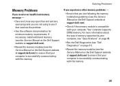
...you experience other memory problems - • Ensure that you are following the memory installation guidelines (see the Service Manual on the Dell Support website at support.dell.com). • Check if the memory module is successfully communicating with the memory. For more information about the... memory. If necessary, install additional memory (see the Service Manual on the Dell Support website at support.dell.com). • Reseat the memory modules (see the Service Manual on the Dell Support website at support.dell.com) to ensure that your computer is compatible with your computer...
...you experience other memory problems - • Ensure that you are following the memory installation guidelines (see the Service Manual on the Dell Support website at support.dell.com). • Check if the memory module is successfully communicating with the memory. For more information about the... memory. If necessary, install additional memory (see the Service Manual on the Dell Support website at support.dell.com). • Reseat the memory modules (see the Service Manual on the Dell Support website at support.dell.com) to ensure that your computer is compatible with your computer...

