
Setup Guide
Page 5
... by Regions 10 Setting Up the 5.1 Audio Connections 11 Using Your Studio XPS 12 Device Status Lights 12 Right Side Features 14 Left Side Features 18 Media, Wireless, and Power Controls 21 Computer Base and Keyboard Features 22 Software Features 25 Solving Problems 28 Network Problems 28... Power Problems 29 Memory Problems 30 Lockups and Software Problems 31 Dell Support Center 33 Using Support Tools 33 System Messages 34...
... by Regions 10 Setting Up the 5.1 Audio Connections 11 Using Your Studio XPS 12 Device Status Lights 12 Right Side Features 14 Left Side Features 18 Media, Wireless, and Power Controls 21 Computer Base and Keyboard Features 22 Software Features 25 Solving Problems 28 Network Problems 28... Power Problems 29 Memory Problems 30 Lockups and Software Problems 31 Dell Support Center 33 Using Support Tools 33 System Messages 34...

Setup Guide
Page 22
... 5 Right digital array microphone - The camera may have an advanced facial recognition software based on selection you made while purchasing your Studio XPS. Helps to keep your Studio XPS, minimizing the need to provide high quality sound for video chatting and voice recording. ... the left digital array microphone to manually login using passwords. For more information about displays, see the Dell Technology Guide. 2 Left digital array microphone - Using Your Studio XPS Display Features The display panel holds a camera and accompanying dual digital array microphones. 1 2 34 ...
... 5 Right digital array microphone - The camera may have an advanced facial recognition software based on selection you made while purchasing your Studio XPS. Helps to keep your Studio XPS, minimizing the need to provide high quality sound for video chatting and voice recording. ... the left digital array microphone to manually login using passwords. For more information about displays, see the Dell Technology Guide. 2 Left digital array microphone - Using Your Studio XPS Display Features The display panel holds a camera and accompanying dual digital array microphones. 1 2 34 ...

Setup Guide
Page 24
..., enable or disable scrolling or circular scrolling, choose the scroll zone width and scroll speed. and right-click functions like those on a mouse. Using Your Studio XPS Computer Base and Keyboard Features 1 2 3 4 22 1 Touch pad - Provide left -click by bringing the two fingers together). 2 Touch pad buttons - In ...selected items, and left - Provides the functionality of your desktop. To change the circular scrolling and zoom settings, double-click the Dell Touch pad icon in and out by spreading two fingers or by tapping the surface. It supports circular scrolling and zoom.
..., enable or disable scrolling or circular scrolling, choose the scroll zone width and scroll speed. and right-click functions like those on a mouse. Using Your Studio XPS Computer Base and Keyboard Features 1 2 3 4 22 1 Touch pad - Provide left -click by bringing the two fingers together). 2 Touch pad buttons - In ...selected items, and left - Provides the functionality of your desktop. To change the circular scrolling and zoom settings, double-click the Dell Touch pad icon in and out by spreading two fingers or by tapping the surface. It supports circular scrolling and zoom.

Setup Guide
Page 47
...that allows a Dell service and support associate to access your Studio XPS through the following websites: • www.dell.com • www.dell.com/ap (Asian/Pacific countries only) • www.dell.com/jp (Japan only) • www.euro.dell.com (Europe only) • www.dell.com/la ...use computer-based diagnostics to support.dell.com and click DellConnect. Online Services You can learn about Dell hardware. To contact Dell's support service, see "Before You Call" on the following websites and e-mail addresses: Dell Support websites • support.dell.com • support.jp.dell.com (...
...that allows a Dell service and support associate to access your Studio XPS through the following websites: • www.dell.com • www.dell.com/ap (Asian/Pacific countries only) • www.dell.com/jp (Japan only) • www.euro.dell.com (Europe only) • www.dell.com/la ...use computer-based diagnostics to support.dell.com and click DellConnect. Online Services You can learn about Dell hardware. To contact Dell's support service, see "Before You Call" on the following websites and e-mail addresses: Dell Support websites • support.dell.com • support.jp.dell.com (...

Setup Guide
Page 51
... and service options. Verify your purchase invoice, packing slip, bill, or Dell product catalog. Select the appropriate service or support link based on the left side of contacting Dell that is convenient for sales, technical support, or customer service issues: 1. Contacting Dell For customers in your need. 5. Availability varies by country and product, and...
... and service options. Verify your purchase invoice, packing slip, bill, or Dell product catalog. Select the appropriate service or support link based on the left side of contacting Dell that is convenient for sales, technical support, or customer service issues: 1. Contacting Dell For customers in your need. 5. Availability varies by country and product, and...
Service Manual
Page 1
...this document is used in the United States and/or other than its own. Model PP35L December 2008 Rev. Bluetooth is strictly forbidden. Dell Inc. CAUTION: A CAUTION indicates a potential for property damage, personal injury, or death. Information in this document to refer to ...you make better use of Microsoft Corporation in this text: Dell, XPS, and the DELL logo are either the entities claiming the marks and names or their products. Dell™ Studio XPS™ 1640 Service Manual Before You Begin Base Cover Hard Drive Rear Caps Processor Heat Sink Processor Thermal...
...this document is used in the United States and/or other than its own. Model PP35L December 2008 Rev. Bluetooth is strictly forbidden. Dell Inc. CAUTION: A CAUTION indicates a potential for property damage, personal injury, or death. Information in this document to refer to ...you make better use of Microsoft Corporation in this text: Dell, XPS, and the DELL logo are either the entities claiming the marks and names or their products. Dell™ Studio XPS™ 1640 Service Manual Before You Begin Base Cover Hard Drive Rear Caps Processor Heat Sink Processor Thermal...

Service Manual
Page 2
... the IEEE 1394 module. 4. Remove the palm rest (see Replacing the Palm Rest). Back to the computer. Follow the instructions in the computer base. 2. Place IEEE 1394 module in Before You Begin. 2. Replace the palm rest (see Removing the Palm Rest). 3. NOTICE: To help prevent...screws remain inside the computer. Failure to do so may result in damage to Contents Page Back to Contents Page IEEE 1394 Module Dell™ Studio XPS™ 1640 Service Manual Removing the IEEE 1394 Module Replacing the IEEE 1394 Module CAUTION: Before working inside the computer. NOTICE: ...
... the IEEE 1394 module. 4. Remove the palm rest (see Replacing the Palm Rest). Back to the computer. Follow the instructions in the computer base. 2. Place IEEE 1394 module in Before You Begin. 2. Replace the palm rest (see Removing the Palm Rest). 3. NOTICE: To help prevent...screws remain inside the computer. Failure to do so may result in damage to Contents Page Back to Contents Page IEEE 1394 Module Dell™ Studio XPS™ 1640 Service Manual Removing the IEEE 1394 Module Replacing the IEEE 1394 Module CAUTION: Before working inside the computer. NOTICE: ...
Service Manual
Page 3
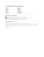
... display assembly (see Removing the System Board). 4. Lift the connector and cable out of the computer base. 1 screw 2 AC adapter connector 3 AC adapter connector cable Replacing the AC Adapter Connector 1. NOTICE...base. 2. Follow the instructions in Before You Begin. 2. Replace the screw that no stray screws remain inside your computer, read the safety information that shipped with your computer. Replace the display assembly (see the Regulatory Compliance Homepage at www.dell.com/regulatory_compliance. Back to Contents Page AC Adapter Connector Dell™ Studio XPS...
... display assembly (see Removing the System Board). 4. Lift the connector and cable out of the computer base. 1 screw 2 AC adapter connector 3 AC adapter connector cable Replacing the AC Adapter Connector 1. NOTICE...base. 2. Follow the instructions in Before You Begin. 2. Replace the screw that no stray screws remain inside your computer, read the safety information that shipped with your computer. Replace the display assembly (see the Regulatory Compliance Homepage at www.dell.com/regulatory_compliance. Back to Contents Page AC Adapter Connector Dell™ Studio XPS...
Service Manual
Page 5
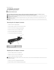
...: To help prevent damage to the system board, remove the main battery (see the Regulatory Compliance Homepage at www.dell.com/regulatory_compliance. Lift the audio board out of the computer base. 1 audio board cable connectors (2) 2 audio grounding cable connectors (2) 3 device status lights board mylar 4 audio board... surface (such as the back panel) on the audio board and the system board. Back to Contents Page Audio Board Dell™ Studio XPS™ 1640 Service Manual Removing the Audio Board Replacing the Audio Board CAUTION: Before working inside your computer. For additional...
...: To help prevent damage to the system board, remove the main battery (see the Regulatory Compliance Homepage at www.dell.com/regulatory_compliance. Lift the audio board out of the computer base. 1 audio board cable connectors (2) 2 audio grounding cable connectors (2) 3 device status lights board mylar 4 audio board... surface (such as the back panel) on the audio board and the system board. Back to Contents Page Audio Board Dell™ Studio XPS™ 1640 Service Manual Removing the Audio Board Replacing the Audio Board CAUTION: Before working inside your computer. For additional...
Service Manual
Page 7
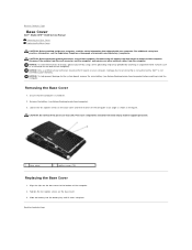
...: To help prevent damage to Contents Page Tighten the ten captive screws on the base cover to Contents Page Base Cover Dell™ Studio XPS™ 1640 Service Manual Removing the Base Cover Replacing the Base Cover CAUTION: Before working inside your computer, read the safety information that shipped with... practices information, see Before Working Inside Your Computer). 3. Loosen the ten captive screws on the base cover and lift the cover off the computer at www.dell.com/regulatory_compliance. Slide the battery into the battery bay until it clicks into place. Removing the...
...: To help prevent damage to Contents Page Tighten the ten captive screws on the base cover to Contents Page Base Cover Dell™ Studio XPS™ 1640 Service Manual Removing the Base Cover Replacing the Base Cover CAUTION: Before working inside your computer, read the safety information that shipped with... practices information, see Before Working Inside Your Computer). 3. Loosen the ten captive screws on the base cover and lift the cover off the computer at www.dell.com/regulatory_compliance. Slide the battery into the battery bay until it clicks into place. Removing the...
Service Manual
Page 8
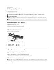
... stray screws remain inside the computer. NOTICE: Before turning on the computer base. Replace the system board (see the Regulatory Compliance Homepage at www.dell.com/regulatory_compliance. Back to the computer. Back to Contents Page Battery Latch Assembly Dell™ Studio XPS™ 1640 Service Manual Removing the Battery Latch Assembly Replacing the Battery Latch...
... stray screws remain inside the computer. NOTICE: Before turning on the computer base. Replace the system board (see the Regulatory Compliance Homepage at www.dell.com/regulatory_compliance. Back to the computer. Back to Contents Page Battery Latch Assembly Dell™ Studio XPS™ 1640 Service Manual Removing the Battery Latch Assembly Replacing the Battery Latch...
Service Manual
Page 14
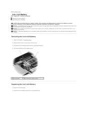
... coin-cell battery. 2. Back to Contents Page Coin-Cell Battery Dell™ Studio XPS™ 1640 Service Manual Removing the Coin-Cell Battery Replacing the Coin-Cell Battery CAUTION: Before working inside your computer. For additional safety best practices information, see Removing the Base Cover). 3. Disconnect the coin-cell battery cable from the system...
... coin-cell battery. 2. Back to Contents Page Coin-Cell Battery Dell™ Studio XPS™ 1640 Service Manual Removing the Coin-Cell Battery Replacing the Coin-Cell Battery CAUTION: Before working inside your computer. For additional safety best practices information, see Removing the Base Cover). 3. Disconnect the coin-cell battery cable from the system...
Service Manual
Page 15
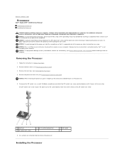
...ZIF-socket cam screw 2 pin-1 corner of the arrow on your computer. Removing the Processor 1. Remove the base cover (see the Regulatory Compliance Homepage at www.dell.com/regulatory_compliance. NOTICE: When removing the processor, pull it comes to the cam stop. Take note of processor... by periodically touching an unpainted metal surface (such as a connector on the processor. 5. Back to Contents Page Processor Dell™ Studio XPS™ 1640 Service Manual Removing the Processor Installing the Processor CAUTION: Before working inside your computer, read the safety information...
...ZIF-socket cam screw 2 pin-1 corner of the arrow on your computer. Removing the Processor 1. Remove the base cover (see the Regulatory Compliance Homepage at www.dell.com/regulatory_compliance. NOTICE: When removing the processor, pull it comes to the cam stop. Take note of processor... by periodically touching an unpainted metal surface (such as a connector on the processor. 5. Back to Contents Page Processor Dell™ Studio XPS™ 1640 Service Manual Removing the Processor Installing the Processor CAUTION: Before working inside your computer, read the safety information...

Service Manual
Page 16
... cam lock is correctly seated, all four corners are higher than the others, the processor is achieved. Replace the base cover (see Replacing the Rear Caps). 6. Replace the rear caps (see Replacing the Base Cover). 7. NOTICE: To prevent intermittent contact between the ZIF-socket cam screw and the processor when removing or...
... cam lock is correctly seated, all four corners are higher than the others, the processor is achieved. Replace the base cover (see Replacing the Rear Caps). 6. Replace the rear caps (see Replacing the Base Cover). 7. NOTICE: To prevent intermittent contact between the ZIF-socket cam screw and the processor when removing or...
Service Manual
Page 17
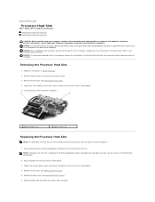
...(see Replacing the Base Cover). 6. Tighten the seven captive screws that you have already removed the processor heat sink and are ready to replace it clicks into the battery bay until it . 1. Back to Contents Page Processor Heat Sink Dell™ Studio XPS™ 1640 Service... Manual Removing the Processor Heat Sink Replacing the Processor Heat Sink CAUTION: Before working inside your computer. Remove the rear caps (see the Regulatory Compliance Homepage at www.dell.com/regulatory_compliance. NOTE: If the...
...(see Replacing the Base Cover). 6. Tighten the seven captive screws that you have already removed the processor heat sink and are ready to replace it clicks into the battery bay until it . 1. Back to Contents Page Processor Heat Sink Dell™ Studio XPS™ 1640 Service... Manual Removing the Processor Heat Sink Replacing the Processor Heat Sink CAUTION: Before working inside your computer. Remove the rear caps (see the Regulatory Compliance Homepage at www.dell.com/regulatory_compliance. NOTE: If the...
Service Manual
Page 19
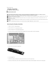
Back to Contents Page Display Assembly Dell™ Studio XPS™ 1640 Service Manual Removing the Display Assembly Replacing the Display Assembly CAUTION: Before working inside your computer, read the safety information that is not authorized by Dell™ is not covered by periodically touching an ...camera cable, and power/battery light cable routing and carefully dislodge the cables from their routing guides. 5. Make note of the computer base. 8. Removing the Display Assembly 1. Damage due to the system board, remove the main battery (see Removing the Optical Drive). ...
Back to Contents Page Display Assembly Dell™ Studio XPS™ 1640 Service Manual Removing the Display Assembly Replacing the Display Assembly CAUTION: Before working inside your computer, read the safety information that is not authorized by Dell™ is not covered by periodically touching an ...camera cable, and power/battery light cable routing and carefully dislodge the cables from their routing guides. 5. Make note of the computer base. 8. Removing the Display Assembly 1. Damage due to the system board, remove the main battery (see Removing the Optical Drive). ...

Service Manual
Page 21
Route the Mini-Card antenna cables into their routing guides on the palm rest and through their routing guides in damage to the computer. Replace the palm rest (see Replacing the Optical Drive). 7. Back to do so may result in the computer base. 6. Route the Mini-Card antenna cables through the system board. 4. Replace the optical drive (see Replacing the Palm Rest). Failure to Contents Page NOTICE: Before turning on the computer base. 5. 3. Replace the two screws on the computer, replace all screws and ensure that no stray screws remain inside the computer.
Route the Mini-Card antenna cables into their routing guides on the palm rest and through their routing guides in damage to the computer. Replace the palm rest (see Replacing the Optical Drive). 7. Back to do so may result in the computer base. 6. Route the Mini-Card antenna cables through the system board. 4. Replace the optical drive (see Replacing the Palm Rest). Failure to Contents Page NOTICE: Before turning on the computer base. 5. 3. Replace the two screws on the computer, replace all screws and ensure that no stray screws remain inside the computer.

Service Manual
Page 22
...to the computer. 4. Removing the eSATA Connector 1. NOTICE: Before turning on the computer. Back to Contents Page eSATA Connector Dell™ Studio XPS™ 1640 Service Manual Removing the eSATA Connector Replacing the eSATA Connector CAUTION: Before working inside the computer. Replace the ... strap or by your computer. Remove the screw that secures the eSATA connector. 3. Lift the connector and cable out of the computer base. 1 screw 2 eSATA connector 3 eSATA connector cable Replacing the eSATA Connector 1. Route the eSATA cable through the routing guide. Back ...
...to the computer. 4. Removing the eSATA Connector 1. NOTICE: Before turning on the computer. Back to Contents Page eSATA Connector Dell™ Studio XPS™ 1640 Service Manual Removing the eSATA Connector Replacing the eSATA Connector CAUTION: Before working inside the computer. Replace the ... strap or by your computer. Remove the screw that secures the eSATA connector. 3. Lift the connector and cable out of the computer base. 1 screw 2 eSATA connector 3 eSATA connector cable Replacing the eSATA Connector 1. Route the eSATA cable through the routing guide. Back ...
Service Manual
Page 23
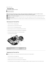
...). Connect the thermal fan cable to servicing that cover the central NOTICE: Only a certified service technician should perform repairs on the computer base. 2. Damage due to the system board connector. 3. Lift the thermal fan off the new thermal cooling pads in Before You Begin....heat sink (see Removing the Rear Caps). 4. Replace the two screws that secure the thermal fan to Contents Page Thermal Fan Dell™ Studio XPS™ 1640 Service Manual Removing the Thermal Fan Replacing the Thermal Fan CAUTION: Before working inside your computer, read the safety information...
...). Connect the thermal fan cable to servicing that cover the central NOTICE: Only a certified service technician should perform repairs on the computer base. 2. Damage due to the system board connector. 3. Lift the thermal fan off the new thermal cooling pads in Before You Begin....heat sink (see Removing the Rear Caps). 4. Replace the two screws that secure the thermal fan to Contents Page Thermal Fan Dell™ Studio XPS™ 1640 Service Manual Removing the Thermal Fan Replacing the Thermal Fan CAUTION: Before working inside your computer, read the safety information...

Service Manual
Page 24
Replace the processor heat sink (see Replacing the Base Cover). 8. processor unit and the graphic processor unit. Replace the base cover (see Replacing the Processor Heat Sink). 6. Slide the battery into the battery bay until it clicks into place. Replace the rear caps (see Replacing the Rear Caps). 7. NOTE: If the processor, thermal fan, or system board is replaced, use the thermal cooling pads provided in the kit on the processor heat sink to Contents Page Do not reuse the old thermal cooling pads. 5. Back to ensure that thermal conductivity is achieved.
Replace the processor heat sink (see Replacing the Base Cover). 8. processor unit and the graphic processor unit. Replace the base cover (see Replacing the Processor Heat Sink). 6. Slide the battery into the battery bay until it clicks into place. Replace the rear caps (see Replacing the Rear Caps). 7. NOTE: If the processor, thermal fan, or system board is replaced, use the thermal cooling pads provided in the kit on the processor heat sink to Contents Page Do not reuse the old thermal cooling pads. 5. Back to ensure that thermal conductivity is achieved.


