
Setup Guide
Page 15
To turn on wireless, with the computer turned on, lightly touch the wireless symbol on the center control cover and then release. Using Your Studio XPS 13 To turn off Bluetooth wireless, either press the wireless symbol or right-click the Bluetooth icon in the notification area of your desktop, and click ...
To turn on wireless, with the computer turned on, lightly touch the wireless symbol on the center control cover and then release. Using Your Studio XPS 13 To turn off Bluetooth wireless, either press the wireless symbol or right-click the Bluetooth icon in the notification area of your desktop, and click ...
Setup Guide
Page 58
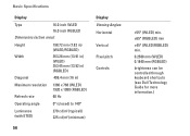
... RGBLED Dimensions (active area): Height 198.72 mm (7.82 in) (WLED/RGBLED) Width Diagonal 353.28 mm (13.91 in) (WLED) 353.45 mm (13.92 in) (RGBLED) 406.4 mm (16 in) Maximum resolution Refresh rate 1366 x 768 (WLED) 1920 x 1080 (RGBLED) 60 Hz Operating angle 0° (closed) to 140° Luminance (with.... ±65° (RGBLED) min ±45° (WLED/RGBLED) min. 0.2588 mm (WLED) 0.1840 mm (RGBLED) brightness can be controlled through keyboard shortcuts (see Dell Technology Guide for more information.)
... RGBLED Dimensions (active area): Height 198.72 mm (7.82 in) (WLED/RGBLED) Width Diagonal 353.28 mm (13.91 in) (WLED) 353.45 mm (13.92 in) (RGBLED) 406.4 mm (16 in) Maximum resolution Refresh rate 1366 x 768 (WLED) 1920 x 1080 (RGBLED) 60 Hz Operating angle 0° (closed) to 140° Luminance (with.... ±65° (RGBLED) min ±45° (WLED/RGBLED) min. 0.2588 mm (WLED) 0.1840 mm (RGBLED) brightness can be controlled through keyboard shortcuts (see Dell Technology Guide for more information.)
Service Manual
Page 28
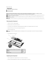
... varies according to region) 3 keyboard 5 keyboard shield 2 palm rest 4 screws (13) Replacing the Keyboard 1. Be careful when removing and handling the keyboard. 6. Back to Contents Page Keyboard Dell™ Studio XPS™ 1640 Service Manual Removing the Keyboard Replacing the Keyboard CAUTION: Before working inside your...are fragile, easily dislodged, and time-consuming to replace. NOTICE: To help prevent damage to servicing that is not authorized by Dell™ is not covered by periodically touching an unpainted metal surface (such as a connector on the palm rest. 2. Damage ...
... varies according to region) 3 keyboard 5 keyboard shield 2 palm rest 4 screws (13) Replacing the Keyboard 1. Be careful when removing and handling the keyboard. 6. Back to Contents Page Keyboard Dell™ Studio XPS™ 1640 Service Manual Removing the Keyboard Replacing the Keyboard CAUTION: Before working inside your...are fragile, easily dislodged, and time-consuming to replace. NOTICE: To help prevent damage to servicing that is not authorized by Dell™ is not covered by periodically touching an unpainted metal surface (such as a connector on the palm rest. 2. Damage ...
Service Manual
Page 43
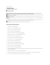
Back to Contents Page System Board Dell™ Studio XPS™ 1640 Service Manual Removing the System Board Replacing...IEEE 1394 module (see Removing the Rear Caps). 4. Remove the rear caps (see Removing the IEEE 1394 Module). 13. Remove the audio board (see Removing the Processor Heat Sink). 7. NOTICE: To avoid electrostatic discharge, ground yourself ...of the computer and out of the computer. Remove the memory module(s) (see Removing the Display Assembly). 16. Disconnect the right power/battery light cable, left power/battery light cable, display cable, and camera ...
Back to Contents Page System Board Dell™ Studio XPS™ 1640 Service Manual Removing the System Board Replacing...IEEE 1394 module (see Removing the Rear Caps). 4. Remove the rear caps (see Removing the IEEE 1394 Module). 13. Remove the audio board (see Removing the Processor Heat Sink). 7. NOTICE: To avoid electrostatic discharge, ground yourself ...of the computer and out of the computer. Remove the memory module(s) (see Removing the Display Assembly). 16. Disconnect the right power/battery light cable, left power/battery light cable, display cable, and camera ...
Service Manual
Page 44
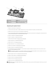
Replace the Mini-Cards, if any (see Replacing the Thermal Fan). 13. Replace the thermal fan (see Replacing the Mini-Card). 11. Do not reuse the old thermal cooling pads. 14. Peel the backing off the new ... the eSATA connector cable, AC adapter connector cable, and TV tuner card cable to the computer. Replace the rear caps (see Replacing the Memory Module(s)). 16. Replace the audio board (see Replacing the Coin-Cell Battery). 12. Replace the coin-cell battery (see Replacing the Audio Board). 6. NOTICE: Before turning on...
Replace the Mini-Cards, if any (see Replacing the Thermal Fan). 13. Replace the thermal fan (see Replacing the Mini-Card). 11. Do not reuse the old thermal cooling pads. 14. Peel the backing off the new ... the eSATA connector cable, AC adapter connector cable, and TV tuner card cable to the computer. Replace the rear caps (see Replacing the Memory Module(s)). 16. Replace the audio board (see Replacing the Coin-Cell Battery). 12. Replace the coin-cell battery (see Replacing the Audio Board). 6. NOTICE: Before turning on...


