Replacing the Hard-Drive Tray
Page 1
... information, see the Service Manual on Your Dell Precision™ Workstation T3500/T5500 WARNING: Before working inside your computer, read the safety information that shipped with your computer. NOTE: For more information on removing and replacing parts on your computer, see the Regulatory Compliance Homepage at support.dell.com/manuals. 1 Turn off your computer...
... information, see the Service Manual on Your Dell Precision™ Workstation T3500/T5500 WARNING: Before working inside your computer, read the safety information that shipped with your computer. NOTE: For more information on removing and replacing parts on your computer, see the Regulatory Compliance Homepage at support.dell.com/manuals. 1 Turn off your computer...

Setup and Features Information Tech Sheet
Page 7
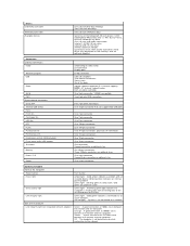
...computer is good - The computer is in normal operating state no light) - solid green for two full height, full length graphics cards using the PCIe x16 graphics card slot two 5.25 inch drive bays and one 3.5 inch drive bay (flex bay) three 3.5 inch SATA drive bays • up...; internal USB Flash Reader • up to three 3.5-inch SATA or SAS hard drives (hard drives may be placed in sleep state; Video Type: Discrete Drives Externally accessible Internally accessible Available devices Controls and Lights Front of the computer: Power button Power light Drive activity light Link integrity...
...computer is good - The computer is in normal operating state no light) - solid green for two full height, full length graphics cards using the PCIe x16 graphics card slot two 5.25 inch drive bays and one 3.5 inch drive bay (flex bay) three 3.5 inch SATA drive bays • up...; internal USB Flash Reader • up to three 3.5-inch SATA or SAS hard drives (hard drives may be placed in sleep state; Video Type: Discrete Drives Externally accessible Internally accessible Available devices Controls and Lights Front of the computer: Power button Power light Drive activity light Link integrity...
Service Manual
Page 12
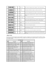
...test in progress 2-1-2 1st 64 K RAM chip or data line failure - bit 2 4-2-2 Shutdown test in progress or video subsystem failure. Solid 3- Solid 4- Off 4- Solid 2- Off 4- Solid 3- Beep Codes When errors occur during a... 3- Solid 1- Solid 2- Off 3- Solid 4- Off 3- Solid 1- Solid 3- Off 4- Solid 2- Solid 2- Solid 3- Solid 4- Solid 2- Solid VID Video Card Video subsystem configuration activity in progress or failure 2-1-4 1st 64 K RAM chip or data line failure - STO Storage Storage device configuration in progress. MEM Memory Memory...
...test in progress 2-1-2 1st 64 K RAM chip or data line failure - bit 2 4-2-2 Shutdown test in progress or video subsystem failure. Solid 3- Solid 4- Off 4- Solid 2- Off 4- Solid 3- Beep Codes When errors occur during a... 3- Solid 1- Solid 2- Off 3- Solid 4- Off 3- Solid 1- Solid 3- Off 4- Solid 2- Solid 2- Solid 3- Solid 4- Solid 2- Solid VID Video Card Video subsystem configuration activity in progress or failure 2-1-4 1st 64 K RAM chip or data line failure - STO Storage Storage device configuration in progress. MEM Memory Memory...
Service Manual
Page 15
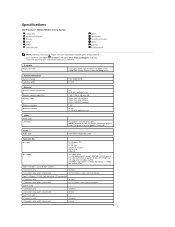
...pins 32 bits One PCI-X slot Connector pins Connector data width (maximum) 188 pins 64 bits Specifications Dell Precision™ T5500/T5500n Service Manual Processors System Information Memory Video Audio Expansion Bus Drives Connectors Controls and Lights Power Physical Environmental NOTE: Offerings may vary by region.... GB with optional riser PCI Express 2.0 x16 (two slots) NOTE: Support for two full height, full length graphics cards using the PCIe x16 graphics card slot. For more information regarding the configuration of your Tablet-PC, click Start (or Start in Windows XP)® ...
...pins 32 bits One PCI-X slot Connector pins Connector data width (maximum) 188 pins 64 bits Specifications Dell Precision™ T5500/T5500n Service Manual Processors System Information Memory Video Audio Expansion Bus Drives Connectors Controls and Lights Power Physical Environmental NOTE: Offerings may vary by region.... GB with optional riser PCI Express 2.0 x16 (two slots) NOTE: Support for two full height, full length graphics cards using the PCIe x16 graphics card slot. For more information regarding the configuration of your Tablet-PC, click Start (or Start in Windows XP)® ...
Service Manual
Page 16
... Amber light Solid amber indicates a problem with an optional adapter) Connectors External connectors: Video Network adapter USB Audio Serial PS/2 System board connectors: Serial ATA Internal USB device Fans: Front fan Card cage fan HDD fan PCI PCI-X PCI Express x8 PCI Express x16 Front panel control... (USB included) Front panel audio HDA header Processor Memory Power 12 V Power (Depending on video card) DVI connector Display port RJ-45 connector USB 2.0 compliant Two internal connectors Two in front Six at 1000Mbs exists between the network and...
... Amber light Solid amber indicates a problem with an optional adapter) Connectors External connectors: Video Network adapter USB Audio Serial PS/2 System board connectors: Serial ATA Internal USB device Fans: Front fan Card cage fan HDD fan PCI PCI-X PCI Express x8 PCI Express x16 Front panel control... (USB included) Front panel audio HDA header Processor Memory Power 12 V Power (Depending on video card) DVI connector Display port RJ-45 connector USB 2.0 compliant Two internal connectors Two in front Six at 1000Mbs exists between the network and...
Service Manual
Page 69
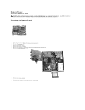
Remove the front fan assembly. 6. Remove any expansion or video cards and raise the expansion card retention arm. 7. For additional safety best practices information, see the Regulatory Compliance Homepage at www.dell.com/regulatory_compliance. Removing the System Board 1. Remove any memory modules. 9. ... audio cable from the system board. Lift the hard drive tray. 4. Remove the memory shroud. 5. System Board Dell Precision™ T5500 Service Manual WARNING: Before working inside your computer, read the safety information that shipped with your computer. Follow the procedures...
Remove the front fan assembly. 6. Remove any expansion or video cards and raise the expansion card retention arm. 7. For additional safety best practices information, see the Regulatory Compliance Homepage at www.dell.com/regulatory_compliance. Removing the System Board 1. Remove any memory modules. 9. ... audio cable from the system board. Lift the hard drive tray. 4. Remove the memory shroud. 5. System Board Dell Precision™ T5500 Service Manual WARNING: Before working inside your computer, read the safety information that shipped with your computer. Follow the procedures...


