Owner's manual
Page 8
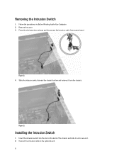
Figure 2. 4. Installing the Intrusion Switch 1. Remove the cover. 3. Figure 3. Connect the intrusion cable to secure it. 2. Slide the intrusion switch toward the chassis bottom and remove it out to the system board. 8 Press the clip inwards to release and disconnect the intrusion cable from the chassis. Insert the intrusion switch into the slot on the back of the chassis and slide it from system board. Follow the procedures in Before Working Inside Your Computer. 2. Removing the Intrusion Switch 1.
Figure 2. 4. Installing the Intrusion Switch 1. Remove the cover. 3. Figure 3. Connect the intrusion cable to secure it. 2. Slide the intrusion switch toward the chassis bottom and remove it out to the system board. 8 Press the clip inwards to release and disconnect the intrusion cable from the chassis. Insert the intrusion switch into the slot on the back of the chassis and slide it from system board. Follow the procedures in Before Working Inside Your Computer. 2. Removing the Intrusion Switch 1.
Owner's manual
Page 9
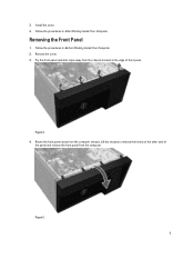
3. Figure 5. 9 Follow the procedures in Before Working Inside Your Computer. 2. Rotate the front panel away from the computer. Removing the Front Panel 1. Pry the front panel retention clips away from the chassis located at the edge of the panel and remove the front panel from the computer chassis. Figure 4. 4. Follow the procedures in After Working Inside Your Computer. Lift the chassis to release the hooks on the other side of front panel. Install the cover. 4. Remove the cover. 3.
3. Figure 5. 9 Follow the procedures in Before Working Inside Your Computer. 2. Rotate the front panel away from the computer. Removing the Front Panel 1. Pry the front panel retention clips away from the chassis located at the edge of the panel and remove the front panel from the computer chassis. Figure 4. 4. Follow the procedures in After Working Inside Your Computer. Lift the chassis to release the hooks on the other side of front panel. Install the cover. 4. Remove the cover. 3.
Owner's manual
Page 10
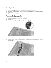
.... 2. Then, ease the card up and out of the front panel into place. 3. Push the panel towards the computer chassis to engage the front-panel retention clips, until they click into the slots on the other side. Remove the cover. 3. Insert the hooks along the ...
.... 2. Then, ease the card up and out of the front panel into place. 3. Push the panel towards the computer chassis to engage the front-panel retention clips, until they click into the slots on the other side. Remove the cover. 3. Insert the hooks along the ...

Owner's manual
Page 15
... the second optical drive (if available). Remove the cover. 3. Figure 12. 6. Disconnect the speaker cable from the system board and release the cable from the chassis clip. 15 Install the: a) front panel b) cover 4. Repeat steps 4 to 6 to the back of the optical drive. 3. Slide the optical drive inside the drive bay...
... the second optical drive (if available). Remove the cover. 3. Figure 12. 6. Disconnect the speaker cable from the system board and release the cable from the chassis clip. 15 Install the: a) front panel b) cover 4. Repeat steps 4 to 6 to the back of the optical drive. 3. Slide the optical drive inside the drive bay...
Owner's manual
Page 16
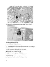
4. Replace the cover. 4. Follow the procedures in Before Working Inside Your Computer. 2. Disconnect and release and the cables from the optical drive(s). 16 Secure the speaker, by sliding it . Press down the speaker-securing tab and slide the speaker upwards to remove it into the chassis clip and connect the speaker cable to the system board. 3. Follow the procedures in After Working Inside Your Computer. Thread the cable into the slot. 2. Removing the Power Supply 1. Remove the cover. 3. Installing the Speakers 1.
4. Replace the cover. 4. Follow the procedures in Before Working Inside Your Computer. 2. Disconnect and release and the cables from the optical drive(s). 16 Secure the speaker, by sliding it . Press down the speaker-securing tab and slide the speaker upwards to remove it into the chassis clip and connect the speaker cable to the system board. 3. Follow the procedures in After Working Inside Your Computer. Thread the cable into the slot. 2. Removing the Power Supply 1. Remove the cover. 3. Installing the Speakers 1.
Owner's manual
Page 19
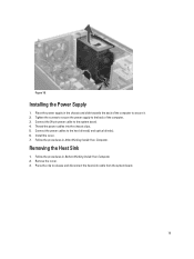
...Supply 1. Install the cover. 7. Remove the cover. 3. Place the power supply in After Working Inside Your Computer. Follow the procedures in the chassis and slide towards the back of the computer. 3. Connect the 24-pin power cable to release and disconnect the heat-sink cable from the .... 4. Follow the procedures in Before Working Inside Your Computer. 2. Connect the power cables to secure it. 2. Thread the power cables into the chassis clips. 5. Removing the Heat Sink 1. Tighten the screws to secure the power supply to the back of the computer to the hard drives(s) and...
...Supply 1. Install the cover. 7. Remove the cover. 3. Place the power supply in After Working Inside Your Computer. Follow the procedures in the chassis and slide towards the back of the computer. 3. Connect the 24-pin power cable to release and disconnect the heat-sink cable from the .... 4. Follow the procedures in Before Working Inside Your Computer. 2. Connect the power cables to secure it. 2. Thread the power cables into the chassis clips. 5. Removing the Heat Sink 1. Tighten the screws to secure the power supply to the back of the computer to the hard drives(s) and...

Owner's manual
Page 20
Connect the heat sink cable to the system board. 3. Installing the Heat Sink 1. Follow the procedures in After Working Inside Your Computer. 20 Install the cover. 5. Place the heat sink into the chassis. 2. Figure 19. 4. Figure 20. Tighten the captive screws to secure the heat sink to the system board. 4. Loosen the captive screws that secure the heat sink to the system board and lift the heat sink away from the computer.
Connect the heat sink cable to the system board. 3. Installing the Heat Sink 1. Follow the procedures in After Working Inside Your Computer. 20 Install the cover. 5. Place the heat sink into the chassis. 2. Figure 19. 4. Figure 20. Tighten the captive screws to secure the heat sink to the system board. 4. Loosen the captive screws that secure the heat sink to the system board and lift the heat sink away from the computer.

Owner's manual
Page 22
... cable from the grommets securing it to the back of the computer. Installing the System Fan 1. Removing the Thermal Sensor 1. Remove the cover. 3. Place the chassis fan in After Working Inside Your Computer. Connect the fan cable to secure in Before Working Inside Your Computer. 2. 4. Follow the procedures in the...
... cable from the grommets securing it to the back of the computer. Installing the System Fan 1. Removing the Thermal Sensor 1. Remove the cover. 3. Place the chassis fan in After Working Inside Your Computer. Connect the fan cable to secure in Before Working Inside Your Computer. 2. 4. Follow the procedures in the...

Owner's manual
Page 23
4. Press the tabs from both sides to release and remove the thermal sensor away from the chassis clip. 5. Release the thermal sensor cable from the chassis. 23
4. Press the tabs from both sides to release and remove the thermal sensor away from the chassis clip. 5. Release the thermal sensor cable from the chassis. 23

Owner's manual
Page 24
Secure the thermal sensor to the slot in on the clip to the system board. 4. Press in the chassis. 2. Follow the procedures in Before Working Inside Your Computer. 2. Remove the: a) cover b) front panel c) optical drive 3. Follow the procedures in After Working Inside Your Computer. Removing the Power Switch 1. Install the cover. 5. Installing the Front Thermal Sensor 1. Connect the thermal sensor cable to release and disconnect the power-switch cable from the system board. 24 Thread the thermal sensor cable into the chassis clip. 3.
Secure the thermal sensor to the slot in on the clip to the system board. 4. Press in the chassis. 2. Follow the procedures in Before Working Inside Your Computer. 2. Remove the: a) cover b) front panel c) optical drive 3. Follow the procedures in After Working Inside Your Computer. Removing the Power Switch 1. Install the cover. 5. Installing the Front Thermal Sensor 1. Connect the thermal sensor cable to release and disconnect the power-switch cable from the system board. 24 Thread the thermal sensor cable into the chassis clip. 3.

Owner's manual
Page 25
Release the power-switch cable from the chassis clips. 25 4.
Release the power-switch cable from the chassis clips. 25 4.

Owner's manual
Page 26
Slide the power switch along with its cable out through the front of the computer. 5. Press the clips on both side of the power switch to release it from the chassis and pull the power switch out of the computer. 26
Slide the power switch along with its cable out through the front of the computer. 5. Press the clips on both side of the power switch to release it from the chassis and pull the power switch out of the computer. 26

Owner's manual
Page 27
... (I /O panel and FlyWire cable from the system board. 27 Disconnect the I /O) Panel 1. Remove the: a) cover b) front panel 3. Connect the power-switch cable to the chassis. 3. Thread the power-switch cable into the chassis clips. 4. Follow the procedures in After Working Inside Your Computer. Secure the power-switch cable to the system board. 5.
... (I /O panel and FlyWire cable from the system board. 27 Disconnect the I /O) Panel 1. Remove the: a) cover b) front panel 3. Connect the power-switch cable to the chassis. 3. Thread the power-switch cable into the chassis clips. 4. Follow the procedures in After Working Inside Your Computer. Secure the power-switch cable to the system board. 5.

Owner's manual
Page 29
... card(s) d) heat sink e) processor 3. Tighten the screw to the chassis. 3. Follow the procedures in Before Working Inside Your Computer. 2. Disconnect all the cables connected to the system board. 6. Slide the I /O panel into the chassis clip. 5. Insert the I /O panel towards the right of the ...computer to secure to secure the I /O panel/FlyWire cable into the slot on the chassis front. 2. Connect the I /O) Panel 1. Install the: a) front panel b) cover 7. Follow the procedures in After Working Inside Your Computer....
... card(s) d) heat sink e) processor 3. Tighten the screw to the chassis. 3. Follow the procedures in Before Working Inside Your Computer. 2. Disconnect all the cables connected to the system board. 6. Slide the I /O panel into the chassis clip. 5. Insert the I /O panel towards the right of the ...computer to secure to secure the I /O panel/FlyWire cable into the slot on the chassis front. 2. Connect the I /O) Panel 1. Install the: a) front panel b) cover 7. Follow the procedures in After Working Inside Your Computer....

Owner's manual
Page 31
Installing the System Board 1. Tighten the screws to secure the system board to the system board. 4. Follow the procedures in the chassis. 2. Connect the cables to the chassis. 3. Install the: a) processor b) heat sink c) expansion card(s) d) front panel e) cover 5. Tilt the system board to the port connectors on the rear of the computer. Align the system board to 45-degrees, and lift the system board out of the chassis and place the system board in After Working Inside Your Computer. 31 6.
Installing the System Board 1. Tighten the screws to secure the system board to the system board. 4. Follow the procedures in the chassis. 2. Connect the cables to the chassis. 3. Install the: a) processor b) heat sink c) expansion card(s) d) front panel e) cover 5. Tilt the system board to the port connectors on the rear of the computer. Align the system board to 45-degrees, and lift the system board out of the chassis and place the system board in After Working Inside Your Computer. 31 6.
Owner's manual
Page 45
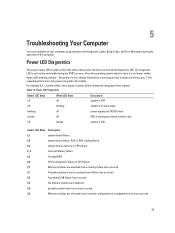
... inserted in sleep state blinking off power supply unit (PSU) failure steady off steady system is only active and visible during the operation of the chassis also functions as a bicolored diagnostic LED. The diagnostic LED is ON Amber LED State Description 2,1 system board failure 2,2 system board failure, PSU or PSU cabling...
... inserted in sleep state blinking off power supply unit (PSU) failure steady off steady system is only active and visible during the operation of the chassis also functions as a bicolored diagnostic LED. The diagnostic LED is ON Amber LED State Description 2,1 system board failure 2,2 system board failure, PSU or PSU cabling...


