
Owner's manual
Page 3
... the Wireless Wide Area Network (WWAN) Card (Optional 16 Removing the Optical Drive...16 Installing the Optical Drive...17 Removing the Primary Hard Drive...18 Installing the Primary Hard Drive...19 Removing the Secondary Hard Drive...19 Installing the Secondary Hard Drive...20 Removing the Coin-Cell Battery...20 Installing the Coin-Cell Battery...21 Removing the Processor Fan...21 Installing the Processor Fan...22...
... the Wireless Wide Area Network (WWAN) Card (Optional 16 Removing the Optical Drive...16 Installing the Optical Drive...17 Removing the Primary Hard Drive...18 Installing the Primary Hard Drive...19 Removing the Secondary Hard Drive...19 Installing the Secondary Hard Drive...20 Removing the Coin-Cell Battery...20 Installing the Coin-Cell Battery...21 Removing the Processor Fan...21 Installing the Processor Fan...22...

Owner's manual
Page 18
... pull out the hard drive from the bracket. Slide the primary hard drive latch to the hard-drive bracket for correct installation of the 7 mm hard drives. 9 mm hard drives does not require the filler when installed into hard-drive bracket. 18 NOTE: A rubber filler is designed to the computer. Removing the Primary Hard Drive 1. Flex the hard-drive bracket outward and pull out the hard drive from the...
... pull out the hard drive from the bracket. Slide the primary hard drive latch to the hard-drive bracket for correct installation of the 7 mm hard drives. 9 mm hard drives does not require the filler when installed into hard-drive bracket. 18 NOTE: A rubber filler is designed to the computer. Removing the Primary Hard Drive 1. Flex the hard-drive bracket outward and pull out the hard drive from the...

Owner's manual
Page 19
... Primary Hard Drive 1. Tighten the screw to secure the primary hard drive to the primary hard . 2. Follow the procedures in place. 3. Pull the tab upward and remove the secondary hard drive from the bracket. 19 Remove the screw that secondary hard drive in After Working Inside Your Computer. Remove the: a) battery b) base cover 3. Remove the secondary hard drive from the computer. 5. Insert the primary hard drive into...
... Primary Hard Drive 1. Tighten the screw to secure the primary hard drive to the primary hard . 2. Follow the procedures in place. 3. Pull the tab upward and remove the secondary hard drive from the bracket. 19 Remove the screw that secondary hard drive in After Working Inside Your Computer. Remove the: a) battery b) base cover 3. Remove the secondary hard drive from the computer. 5. Insert the primary hard drive into...

Owner's manual
Page 20
... secure the secondary hard drive in Before Working Inside Your Computer. 2. Removing the Coin-Cell Battery 1. Engage the secondary hard drive bracket to the secondary hard drive. 2. Follow the procedures in the computer. 5. Pry the coin-cell battery upward and remove it from the computer. 20 Installing the Secondary Hard Drive 1. Install the secondary hard drive into the computer. 4. Remove the: a) battery b) base...
... secure the secondary hard drive in Before Working Inside Your Computer. 2. Removing the Coin-Cell Battery 1. Engage the secondary hard drive bracket to the secondary hard drive. 2. Follow the procedures in the computer. 5. Pry the coin-cell battery upward and remove it from the computer. 20 Installing the Secondary Hard Drive 1. Install the secondary hard drive into the computer. 4. Remove the: a) battery b) base...

Owner's manual
Page 34
... b) battery 7. Align the display brackets to the palmrest. 4. Tighten the screws to secure the display panel to the display panel. 3. Remove the: a) battery b) base cover c) keyboard trim d) keyboard e) optical drive f) primary hard drive g) secondary hard drive 3. Align the display panel in Before Working Inside Your Computer. 2. Disconnect the smart card cable. 34 Tighten the screws to...
... b) battery 7. Align the display brackets to the palmrest. 4. Tighten the screws to secure the display panel to the display panel. 3. Remove the: a) battery b) base cover c) keyboard trim d) keyboard e) optical drive f) primary hard drive g) secondary hard drive 3. Align the display panel in Before Working Inside Your Computer. 2. Disconnect the smart card cable. 34 Tighten the screws to...

Owner's manual
Page 39
Remove the: a) ExpressCard b) battery c) base cover d) keyboard trim e) keyboard f) optical drive g) primary and secondary hard drive h) palm rest 3. Tighten the screw at the bottom of the computer. 6. Disconnect the ExpressCard cables ... in place. 2. Connect the following cables: a) bluetooth module b) power button c) touchpad d) media board e) speaker 4. Install the: a) secondary hard drive b) primary hard drive c) optical drive d) keyboard e) keyboard trim f) base cover g) battery 8. Connect the smart card cable and affix the adhesive tape that secures the palmrest to the...
Remove the: a) ExpressCard b) battery c) base cover d) keyboard trim e) keyboard f) optical drive g) primary and secondary hard drive h) palm rest 3. Tighten the screw at the bottom of the computer. 6. Disconnect the ExpressCard cables ... in place. 2. Connect the following cables: a) bluetooth module b) power button c) touchpad d) media board e) speaker 4. Install the: a) secondary hard drive b) primary hard drive c) optical drive d) keyboard e) keyboard trim f) base cover g) battery 8. Connect the smart card cable and affix the adhesive tape that secures the palmrest to the...

Owner's manual
Page 40
...: a) palm rest b) primary and secondary hard drive c) optical drive d) keyboard e) keyboard trim f) base cover g) battery h) ExpressCard 5. Follow the procedures in After Working Inside Your Computer. 4. Connect the ExpressCard cables to the computer 3. Tighten the screws to secure the ExpressCard module to the system board and the smart card. 4. Remove the screws that secure the...
...: a) palm rest b) primary and secondary hard drive c) optical drive d) keyboard e) keyboard trim f) base cover g) battery h) ExpressCard 5. Follow the procedures in After Working Inside Your Computer. 4. Connect the ExpressCard cables to the computer 3. Tighten the screws to secure the ExpressCard module to the system board and the smart card. 4. Remove the screws that secure the...

Owner's manual
Page 41
Disconnect the camera cable and loosen the captive screws that secure the heat sink to the computer. 3. Remove the heat sink from the computer. Tighten the captive screws to secure the heat sink to the computer. 4. Install the: a) processor fan b) palm rest c) primary and secondary hard drive d) optical drive e) keyboard 41 Connect the camera cable to the system board. 4. a) battery b) base cover c) keyboard trim d) keyboard e) optical drive f) primary and secondary hard drive g) palm rest h) processor fan 3. Replace the heat sink in its slot. 2. Installing the Heat Sink 1.
Disconnect the camera cable and loosen the captive screws that secure the heat sink to the computer. 3. Remove the heat sink from the computer. Tighten the captive screws to secure the heat sink to the computer. 4. Install the: a) processor fan b) palm rest c) primary and secondary hard drive d) optical drive e) keyboard 41 Connect the camera cable to the system board. 4. a) battery b) base cover c) keyboard trim d) keyboard e) optical drive f) primary and secondary hard drive g) palm rest h) processor fan 3. Replace the heat sink in its slot. 2. Installing the Heat Sink 1.

Owner's manual
Page 42
... processor cam lock in Before Working Inside Your Computer. 2. Follow the procedures in a clockwise direction. 3. Follow the procedures in After Working Inside Your Computer. Remove the: a) battery b) base cover c) keyboard trim d) keyboard e) optical drive f) primary and secondary hard drive g) palm rest h) processor fan i) heat sink 3. Follow the procedures in Before Working Inside Your Computer...
... processor cam lock in Before Working Inside Your Computer. 2. Follow the procedures in a clockwise direction. 3. Follow the procedures in After Working Inside Your Computer. Remove the: a) battery b) base cover c) keyboard trim d) keyboard e) optical drive f) primary and secondary hard drive g) palm rest h) processor fan i) heat sink 3. Follow the procedures in Before Working Inside Your Computer...

Owner's manual
Page 43
Tighten the captive screws to the computer. 4. Loosen the captive screws that secures the video-card heatsink to secure the heatsink. 43 Place the heatsink on its original position in the computer. 2. Remove the video-card heatsink from the computer. Installing the Video-Card Heatsink 1. b) bottom door c) keyboard trim d) keyboard e) optical drive f) primary and secondary hard drive g) palmrest h) video-card fan i) heatsink 3.
Tighten the captive screws to the computer. 4. Loosen the captive screws that secures the video-card heatsink to secure the heatsink. 43 Place the heatsink on its original position in the computer. 2. Remove the video-card heatsink from the computer. Installing the Video-Card Heatsink 1. b) bottom door c) keyboard trim d) keyboard e) optical drive f) primary and secondary hard drive g) palmrest h) video-card fan i) heatsink 3.

Owner's manual
Page 44
.... Install the: a) heatsink b) video-card fan c) palmrest d) primary and secondary hard drive e) optical drive f) keyboard g) keyboard trim h) base cover i) battery 4. Removing the Video Card 1. Tighten the screws to secure it to the computer. Remove the: a) battery b) base cover c) keyboard trim d) keyboard e) optical drive f) primary and secondary hard drive g) palm rest h) video-card fan i) video-card heat sink j) heatsink...
.... Install the: a) heatsink b) video-card fan c) palmrest d) primary and secondary hard drive e) optical drive f) keyboard g) keyboard trim h) base cover i) battery 4. Removing the Video Card 1. Tighten the screws to secure it to the computer. Remove the: a) battery b) base cover c) keyboard trim d) keyboard e) optical drive f) primary and secondary hard drive g) palm rest h) video-card fan i) video-card heat sink j) heatsink...

Owner's manual
Page 45
... Inside Your Computer. Lift the right edge of the I /O) Board 1. Remove the: a) SD card b) battery c) base cover d) keyboard trim e) keyboard f) optical drive g) primary and secondary hard drive h) palmrest 3. Remove the screws that secure the I/O board to disengage the connector and remove it from the system board. 4. e) primary and secondary hard drive f) optical drive g) keyboard h) keyboard trim i) base cover j) battery 4.
... Inside Your Computer. Lift the right edge of the I /O) Board 1. Remove the: a) SD card b) battery c) base cover d) keyboard trim e) keyboard f) optical drive g) primary and secondary hard drive h) palmrest 3. Remove the screws that secure the I/O board to disengage the connector and remove it from the system board. 4. e) primary and secondary hard drive f) optical drive g) keyboard h) keyboard trim i) base cover j) battery 4.

Owner's manual
Page 46
Removing the Display Assembly 1. Install the: a) palmrest b) primary and secondary hard drive c) optical drive d) keyboard e) keyboard trim f) base cover g) battery h) SD card 5. Installing the I /O board to the computer. 3. Connect the I/O board connector and... the ExpressCard module connector. 4. Follow the procedures in the computer. 2. Follow the procedures in After Working Inside Your Computer. Remove the: a) battery b) base cover c) keyboard trim d) keyboard e) optical drive f) primary and secondary hard drive g) palmrest 46 Tighten the screws to secure the I /O Board 1.
Removing the Display Assembly 1. Install the: a) palmrest b) primary and secondary hard drive c) optical drive d) keyboard e) keyboard trim f) base cover g) battery h) SD card 5. Installing the I /O board to the computer. 3. Connect the I/O board connector and... the ExpressCard module connector. 4. Follow the procedures in the computer. 2. Follow the procedures in After Working Inside Your Computer. Remove the: a) battery b) base cover c) keyboard trim d) keyboard e) optical drive f) primary and secondary hard drive g) palmrest 46 Tighten the screws to secure the I /O Board 1.

Owner's manual
Page 49
... through the routing channels. 5. Follow the procedures in After Working Inside Your Computer. 2. Removing the Display Hinges and Hinge Towers 1. Installing the Display Assembly 1. Remove the: 49 Tighten the screws at the bottom and back of the computer. 7. Follow the... the computer (for M6700 only). 4. NOTE: LVDS cable is available in place. 2. Tighten the screws to their connectors. 8. Route and connect the antenna cables to secure the display assembly in M6700 only. 3. Install the: a) palmrest b) primary and secondary hard drive c) optical drive d) keyboard e) keyboard...
... through the routing channels. 5. Follow the procedures in After Working Inside Your Computer. 2. Removing the Display Hinges and Hinge Towers 1. Installing the Display Assembly 1. Remove the: 49 Tighten the screws at the bottom and back of the computer. 7. Follow the... the computer (for M6700 only). 4. NOTE: LVDS cable is available in place. 2. Tighten the screws to their connectors. 8. Route and connect the antenna cables to secure the display assembly in M6700 only. 3. Install the: a) palmrest b) primary and secondary hard drive c) optical drive d) keyboard e) keyboard...

Owner's manual
Page 50
... that secure the hinge cover to the computer. Remove the: a) battery b) base cover c) keyboard trim d) keyboard e) optical drive f) primary and secondary hard drive g) display assembly 3. Remove the left display hinge and the left hinge tower from the computer. 50 ...and 2 to secure the left hinge tower and the left display hinge to the computer. 4. Removing the Hinge Cover 1. Install the: a) display bezel b) display assembly c) palmrest d) primary and secondary hard drive e) optical drive f) keyboard g) keyboard trim h) base cover i) battery 5. a) battery b) base cover c) ...
... that secure the hinge cover to the computer. Remove the: a) battery b) base cover c) keyboard trim d) keyboard e) optical drive f) primary and secondary hard drive g) display assembly 3. Remove the left display hinge and the left hinge tower from the computer. 50 ...and 2 to secure the left hinge tower and the left display hinge to the computer. 4. Removing the Hinge Cover 1. Install the: a) display bezel b) display assembly c) palmrest d) primary and secondary hard drive e) optical drive f) keyboard g) keyboard trim h) base cover i) battery 5. a) battery b) base cover c) ...
Owner's manual
Page 51
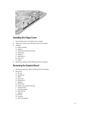
... Installing the Hinge Cover 1. Install the: a) display assembly b) palmrest c) primary and secondary hard drive d) optical drive e) keyboard f) keyboard trim g) base cover h) battery 4. Follow the procedures in After Working Inside Your Computer. Place the hinge cover in its position on the computer. 2. Removing the System Board 1. Tighten the screws to secure the hinge cover to...
... Installing the Hinge Cover 1. Install the: a) display assembly b) palmrest c) primary and secondary hard drive d) optical drive e) keyboard f) keyboard trim g) base cover h) battery 4. Follow the procedures in After Working Inside Your Computer. Place the hinge cover in its position on the computer. 2. Removing the System Board 1. Tighten the screws to secure the hinge cover to...
Owner's manual
Page 55
... Port 1. Disconnect the power-connector cable from the system board and remove the power connector port from the computer. 55 Install the: a) I /O board i) display assembly 3. Remove the: a) battery b) base cover c) keyboard trim d) keyboard e) optical drive f) primary and secondary hard drive g) palmrest h) I /O board b) video card c) video-card heat.... 2. d) processor e) heatsink f) palmrest g) video-card fan h) secondary memory i) primary memory j) primary and secondary hard drive k) optical drive l) keyboard m) keyboard trim n) base cover o) battery p) ExpressCard q) SD card 7.
... Port 1. Disconnect the power-connector cable from the system board and remove the power connector port from the computer. 55 Install the: a) I /O board i) display assembly 3. Remove the: a) battery b) base cover c) keyboard trim d) keyboard e) optical drive f) primary and secondary hard drive g) palmrest h) I /O board b) video card c) video-card heat.... 2. d) processor e) heatsink f) palmrest g) video-card fan h) secondary memory i) primary memory j) primary and secondary hard drive k) optical drive l) keyboard m) keyboard trim n) base cover o) battery p) ExpressCard q) SD card 7.

Owner's manual
Page 56
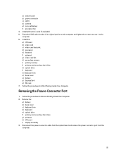
...slot and connect the power-connector cable to the computer and remove it from the computer. 56 Remove the: a) battery b) base cover c) keyboard trim d) keyboard e) optical drive f) primary and secondary hard drive g) palmrest 3. Remove the screws that secure the switch board to the system ...2. Disconnect the switch-board cable from the system board and remove it from the latches. Installing the Power Connector Port 1. Install the: a) display assembly b) I/O board c) palmrest d) primary and secondary hard drive e) optical drive f) keyboard g) keyboard trim h) base cover i) battery 3. ...
...slot and connect the power-connector cable to the computer and remove it from the computer. 56 Remove the: a) battery b) base cover c) keyboard trim d) keyboard e) optical drive f) primary and secondary hard drive g) palmrest 3. Remove the screws that secure the switch board to the system ...2. Disconnect the switch-board cable from the system board and remove it from the latches. Installing the Power Connector Port 1. Install the: a) display assembly b) I/O board c) palmrest d) primary and secondary hard drive e) optical drive f) keyboard g) keyboard trim h) base cover i) battery 3. ...

Owner's manual
Page 59
...), when the Dell logo appears, you can: • Access System Setup by pressing key • Bring up the one-time boot menu by pressing key The one-time boot menu displays the devices that you can : • Change the NVRAM settings after you add or remove hardware •...hard drive). The boot sequence screen also displays the option to access the System Setup screen. The boot-menu options are recorded but do not take effect until you restart the system. NOTE: For most of the system setup options, changes that you make are : • Removable Drive (if available) • STXXXX Drive...
...), when the Dell logo appears, you can: • Access System Setup by pressing key • Bring up the one-time boot menu by pressing key The one-time boot menu displays the devices that you can : • Change the NVRAM settings after you add or remove hardware •...hard drive). The boot sequence screen also displays the option to access the System Setup screen. The boot-menu options are recorded but do not take effect until you restart the system. NOTE: For most of the system setup options, changes that you make are : • Removable Drive (if available) • STXXXX Drive...

Statement of Volatility
Page 2
... settings, PXE settings. various sizes in off state. Volatile memory in GB. Hard drive(s) User Non Volatile magnetic media, Yes replaceable - May also one or two. User Non Volatile optical media. Primary power loss (unplugging the power cord and removing the battery) destroys all user data on the system board lose data if... Serial Flash Memory UH4 Non Volatile memory, built in No PCH, for external data Remedial Action (Action necessary to prevent loss of -day information. 2012 Dell Inc.
... settings, PXE settings. various sizes in off state. Volatile memory in GB. Hard drive(s) User Non Volatile magnetic media, Yes replaceable - May also one or two. User Non Volatile optical media. Primary power loss (unplugging the power cord and removing the battery) destroys all user data on the system board lose data if... Serial Flash Memory UH4 Non Volatile memory, built in No PCH, for external data Remedial Action (Action necessary to prevent loss of -day information. 2012 Dell Inc.


